Bakeneko Build Guide
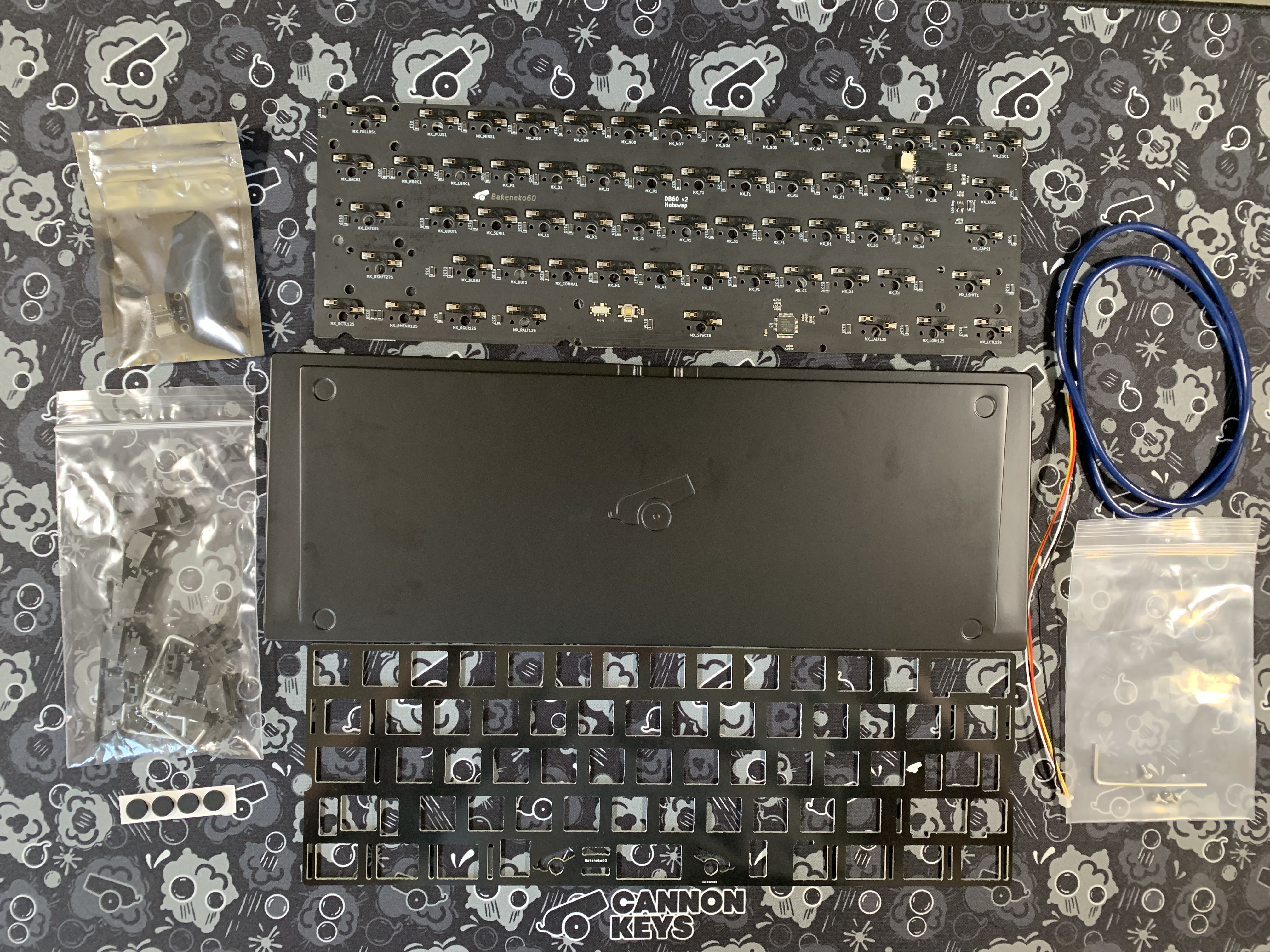
First make sure we have all the items we'll need. Each Bakeneko needs
- A PCB
- A Plate
- USB-C Daughterboard
- JST Cable
- 4xM2 screws (For the Daughterboard)
- Hex Key (for the Screws)
- Silicone O-ring
- Clip-in Stabilizers (typically 4x2U and 1x6.25U for Bakeneko60, and 3x2U and 1x6.25U for Bakeneko65)
- 4 x Silicone Feet
- Bakeneko Aluminum Case
If you're building a BakenekoGO you will also have a battery included, along with a small piece of double-sided tape for installation. You will also have a Molex cable instead of a JST cable.
Note
You must use clip in stabilizers for the Bakeneko as screw in stabilizers will interfere with the O ring
PCB Notice
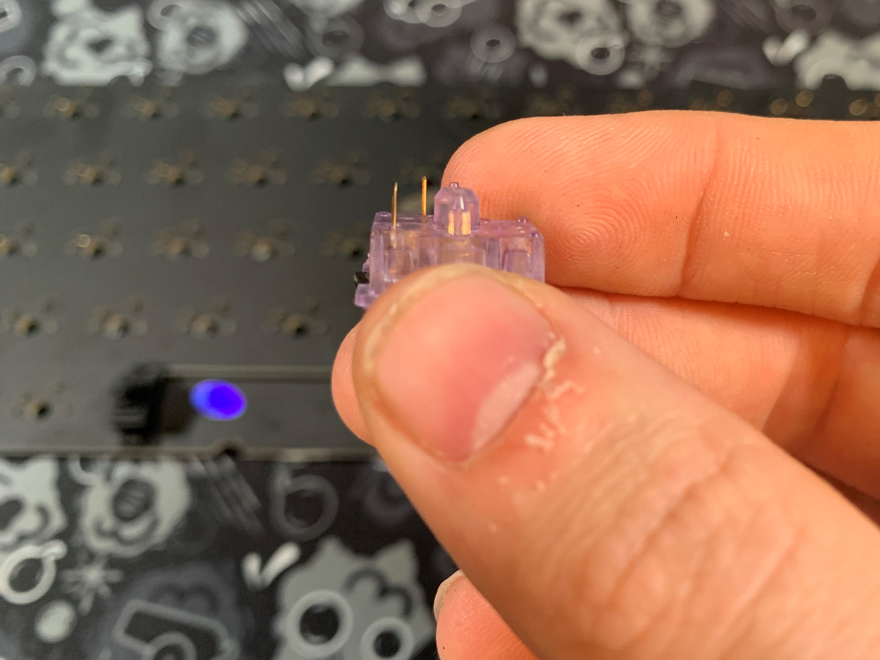
Bakeneko60 and 65 PCBs come preflashed with VIA compatible firmware. But make sure the switch on the back is set to "0". If it is set to "1", your PCB will be stuck in the failsafe flashing mode. It is highly recommended to test the PCB prior to building by using tweezers. The Bakeneko65 PCB will show up as Instant65 or Savage65 in VIA depending on if you are using the hotswap or solderable PCB. This does not effect function, it's just what VIA refers to the PCB as.
BakenekoGO comes with ZMK firmware, which can be flashed and remapped using our Flashing/Remapping Guide. For more information on the BakenekoGO's BT PCB, please see our User Guide.
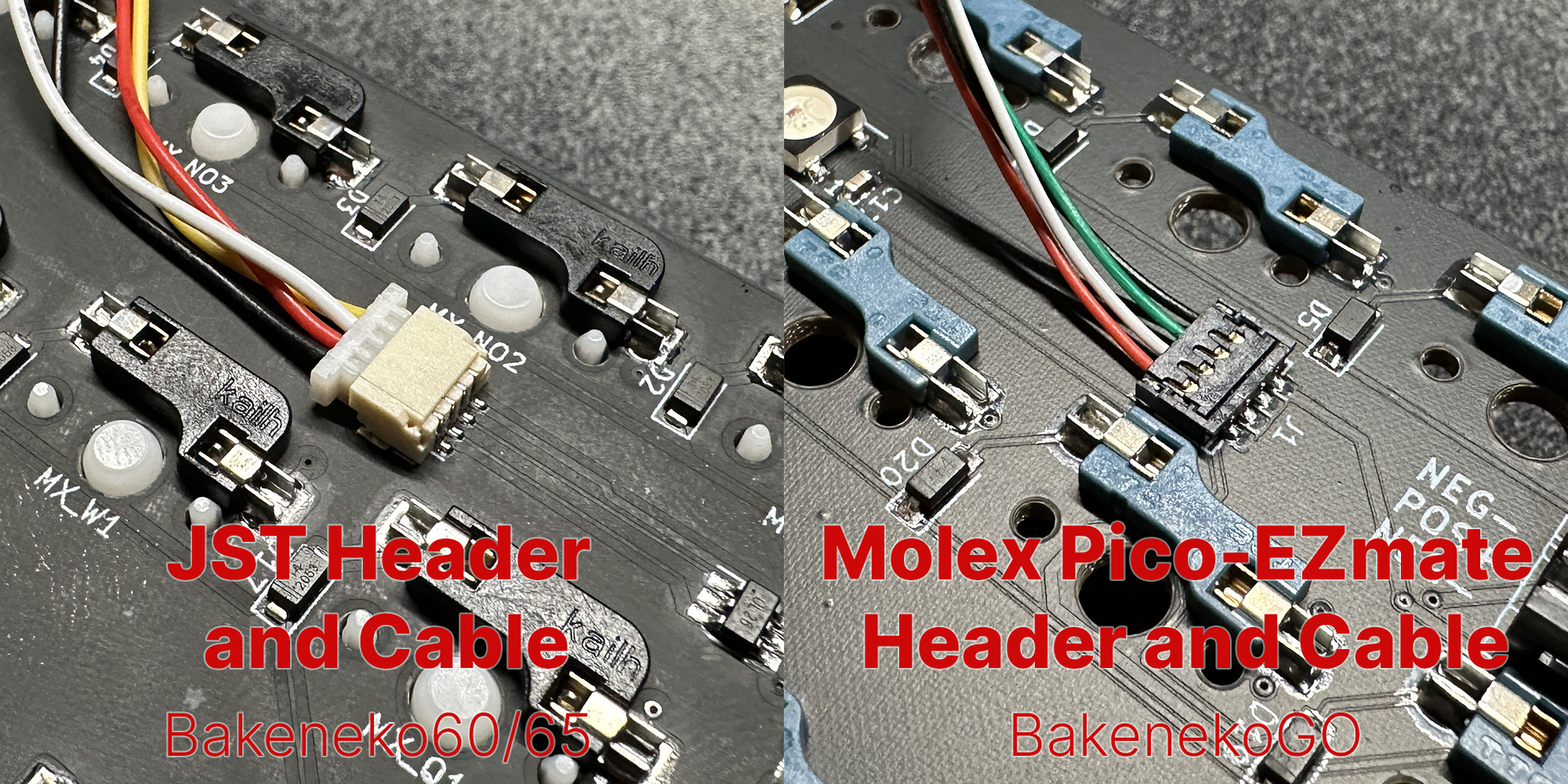
The Bakeneko60 and 65 PCBs and daughterboards use a JST cable and header to connect the PCB to the daughterboard. The BakenekoGO uses a Molex Pico-EZmate header and cable to connect the PCB to the daughterboard.
Building a Bakeneko
- Starting Kit:
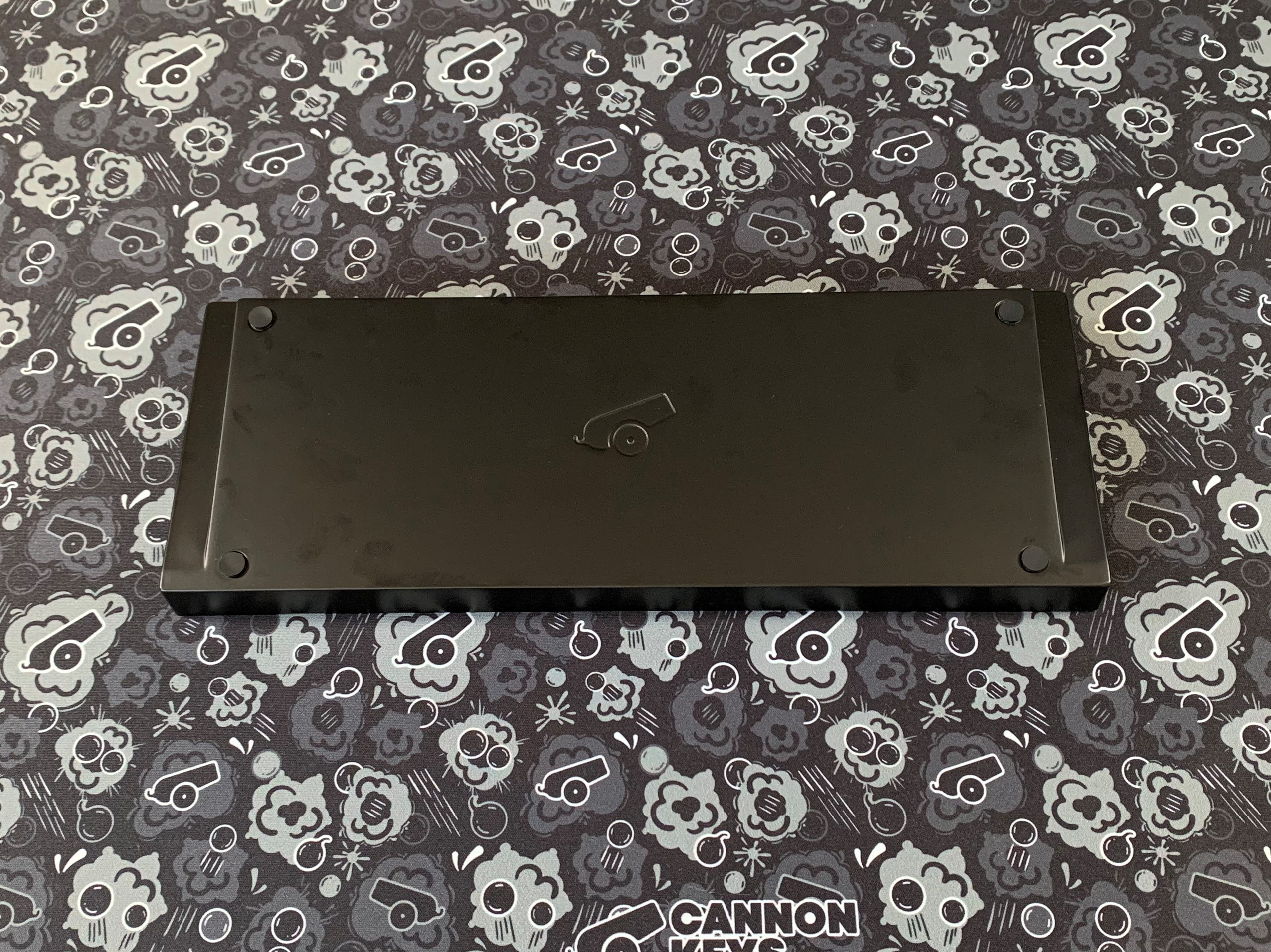
- To help protect the painted finish: flip the keyboard over and install the 4 feet into the indents on the bottom of the case.
Installing the Daughterboard
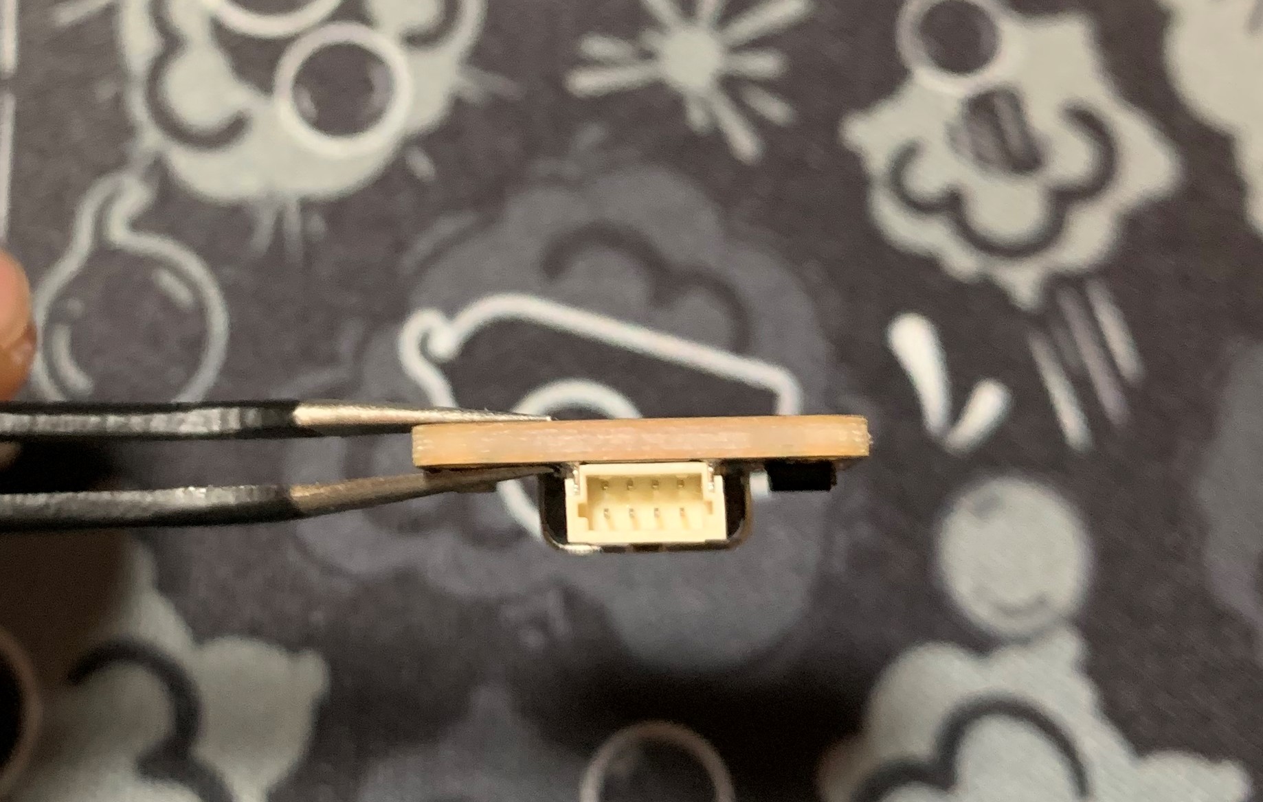
- We are going to add the daughterboard to the case. Check out your daughterboard and look at how the pins are aligned. Here, they are closer to the top.
- Check out your JST cable if your keyboard uses one, and make sure the holes will align with the daughterboard pins.
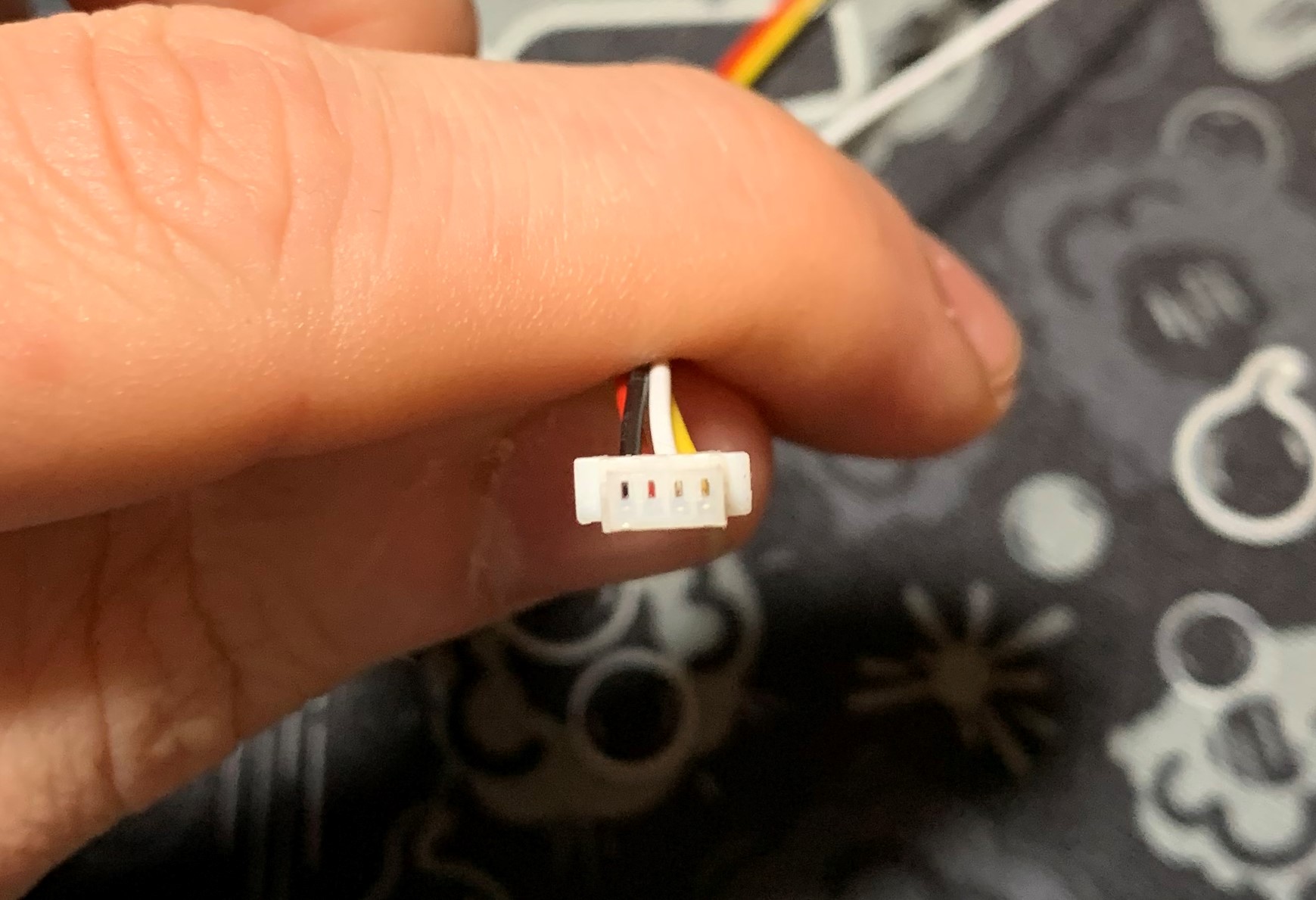
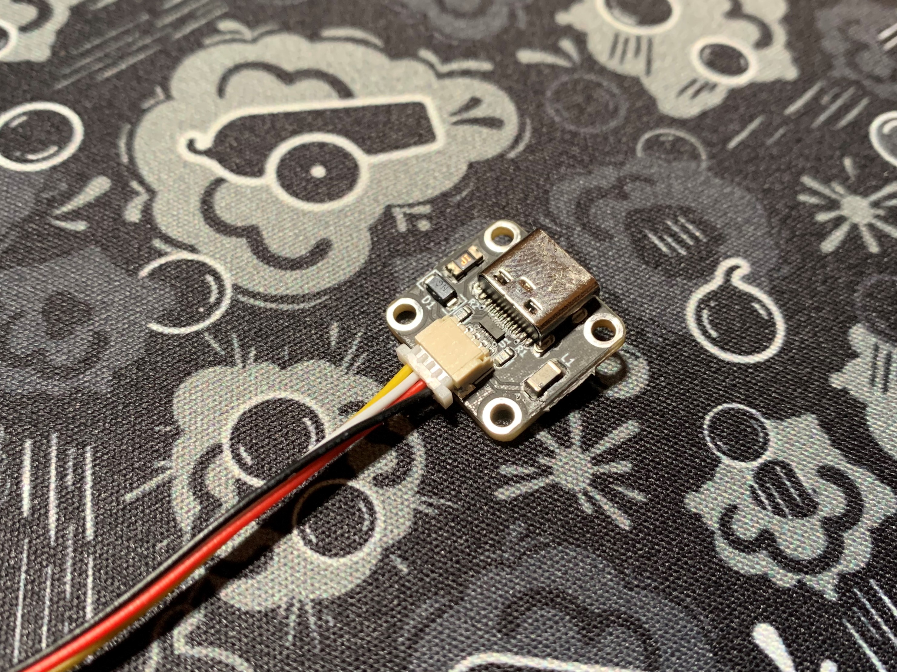
- Insert the JST or Molex cable into the daughterboard, keeping in mind the holes of the cable need to align with the pins on the DB.
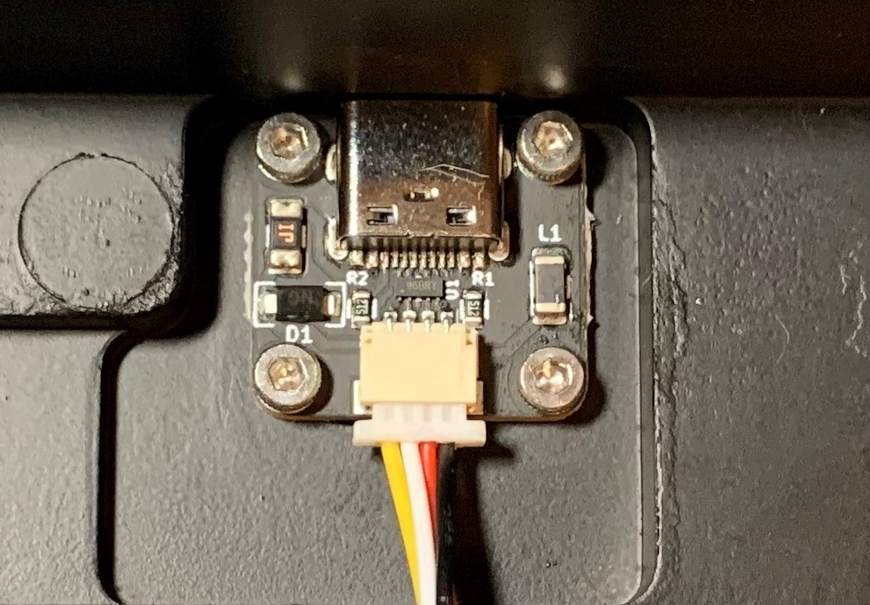
- Using the 4 M2 screws and hex key, screw the daughterboard into the Bakeneko case. Set the case/DB assembly aside.
Preparing your Stabilizers
Note
If you've never prepared stabilizers before, it may be easier to watch a video guide on stabilizers before continuing. We always recommend clipping and lubing stabilizers before using them in a build!
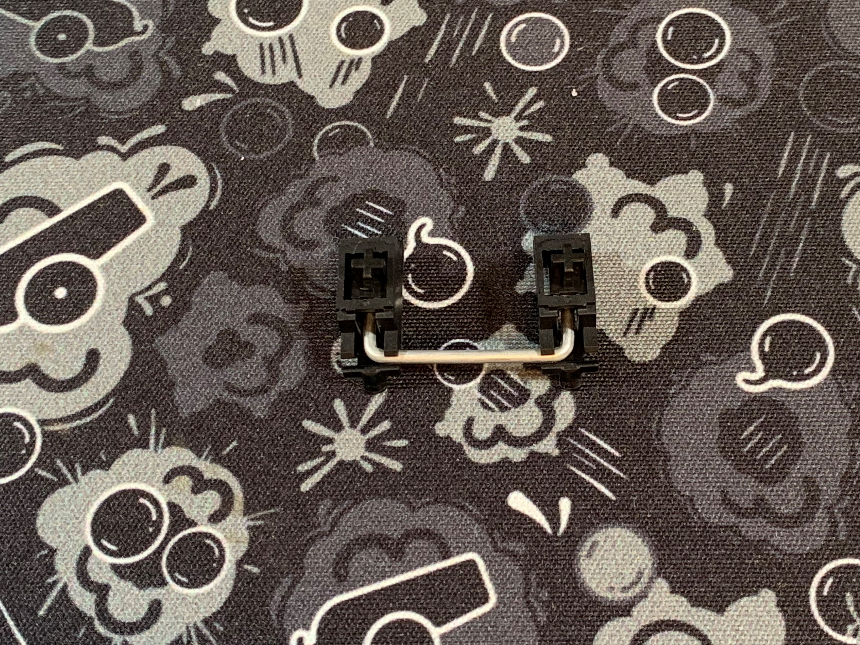
- Align your stabilizer stem so that the portion with 2 holes is facing outwards.
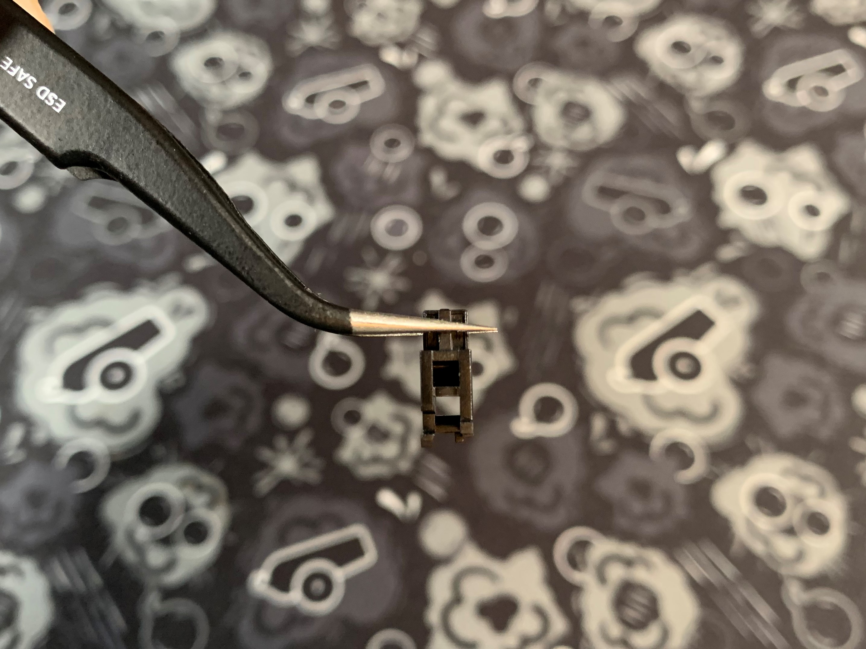
- The 2 holes in the stem will face out of this hole in the housing.
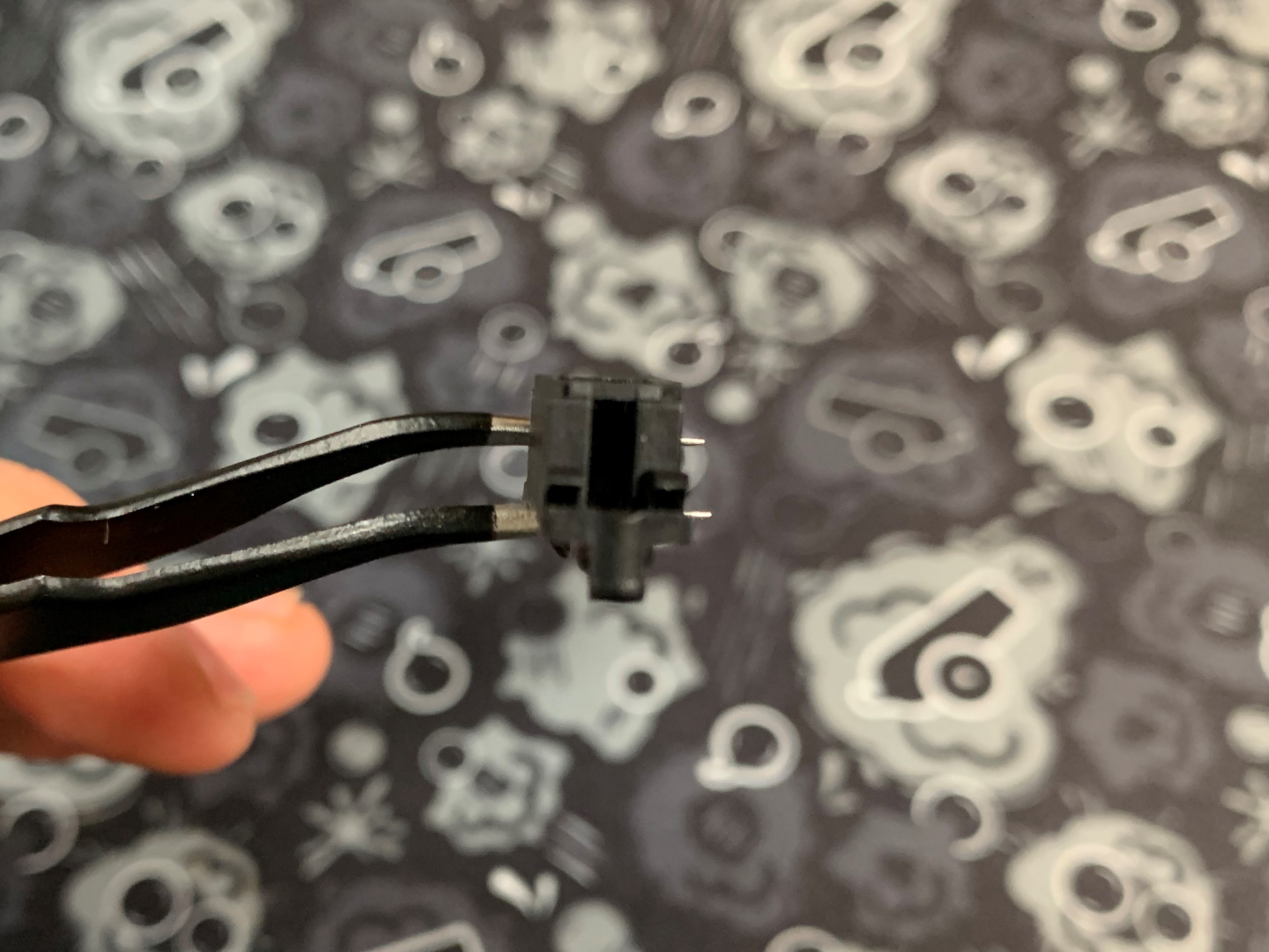
- Put the stem in the housing. Notice how you can see both holes here. (Or rather - the little plastic piece separating the holes)
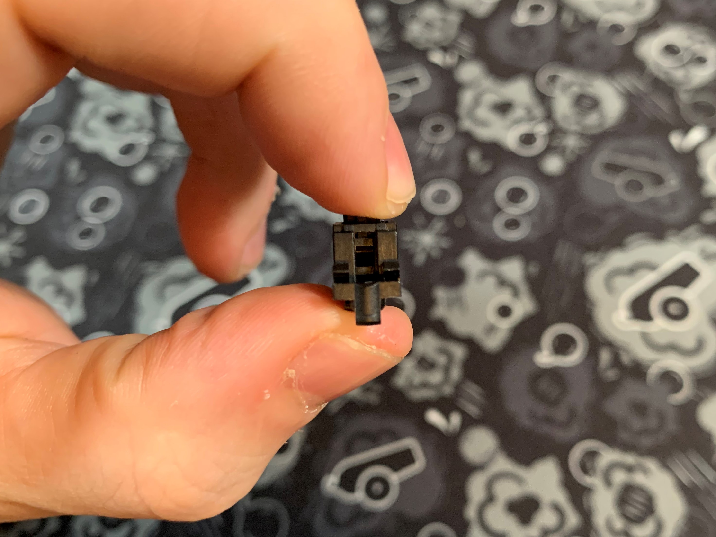
- Insert the stab wire into the bottom hole and clip the wire into the stabilizer housing. If you're having trouble with this step, watch the video linked above!
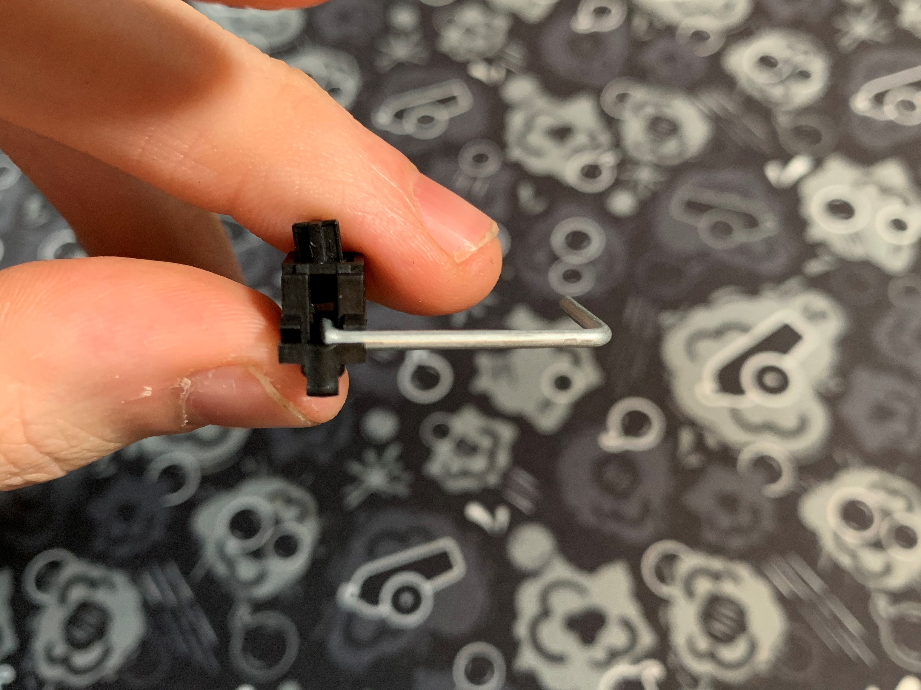
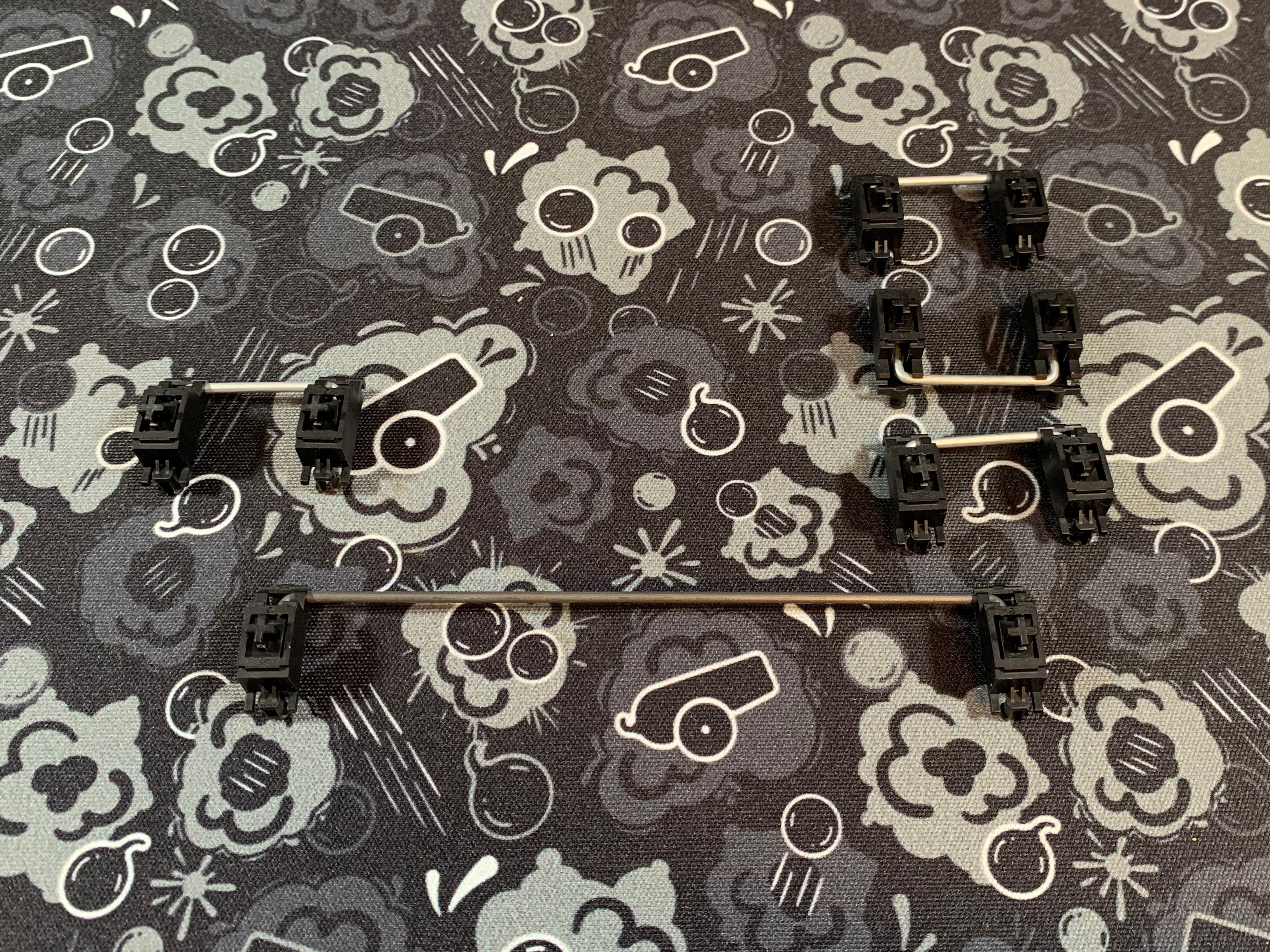
- Repeat the process for the other side and finish assembling your stabilizer.
- Repeat the process for all of the other stabilizers.
Preparing the PCB/Plate Assembly
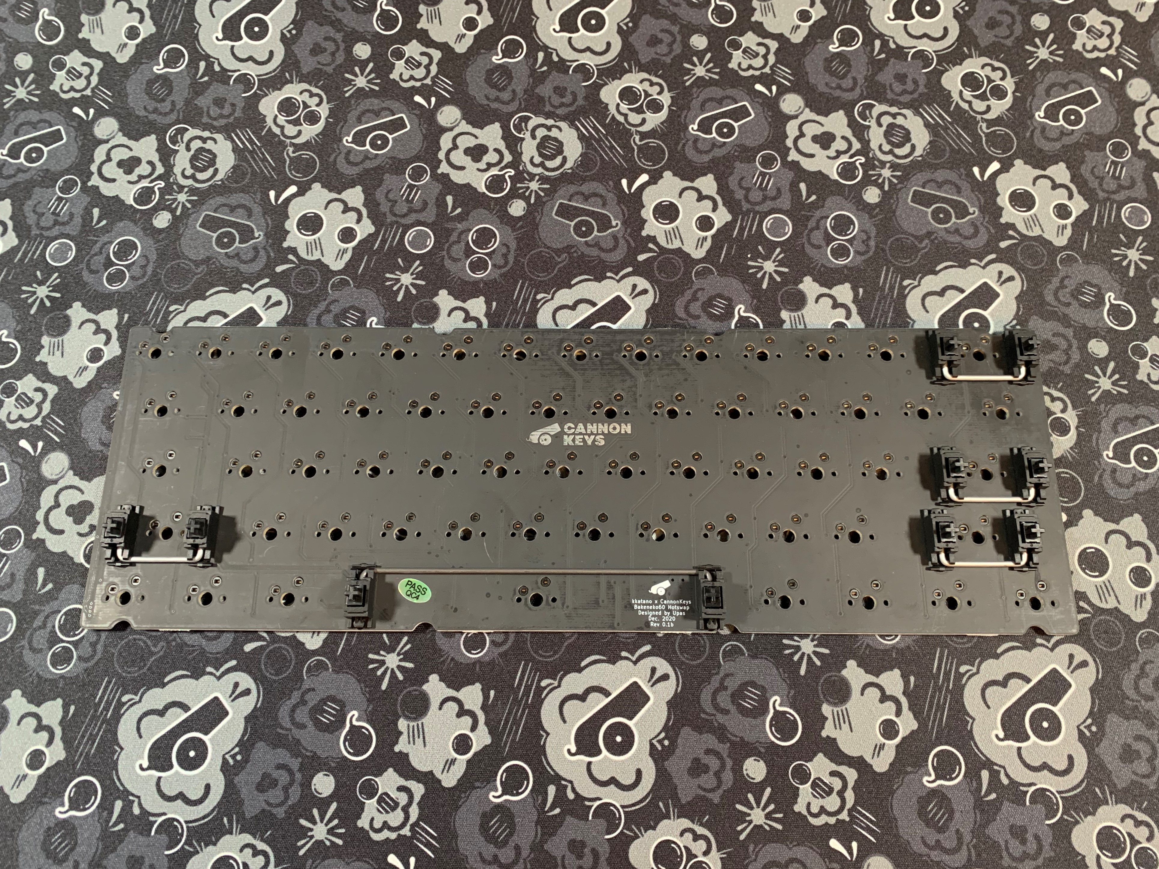
- Install all the stabilizers into the PCB. The front of the stabilizer should go into the larger holes, allowing the back to clip into the smaller ones.
- Before inserting any switches, make sure the pins are straight.
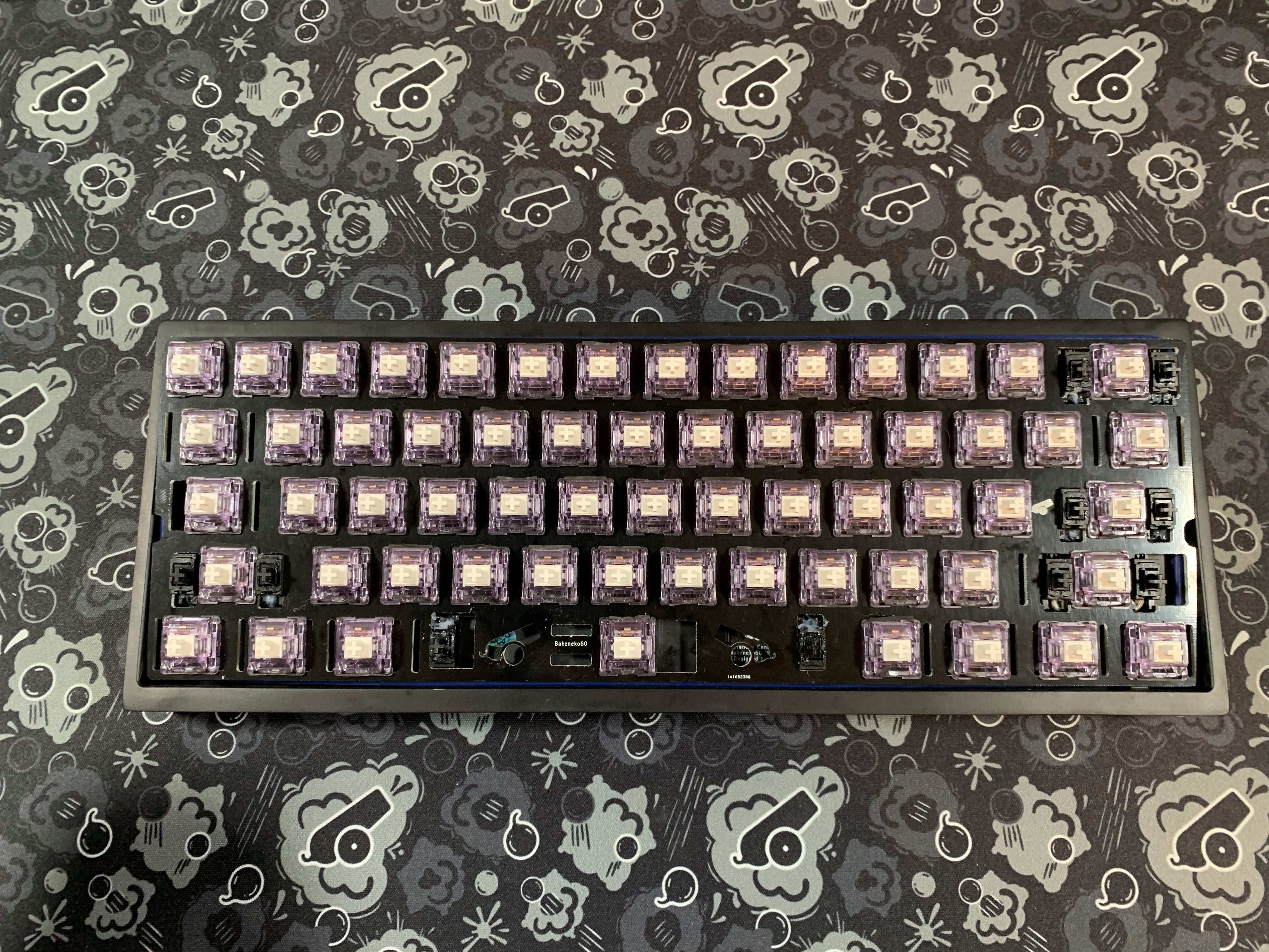
- Now we are going to add switches to our PCB. Insert 6 or so switches along the outside of the plate, then place the plate ontop of the PCB. Don't push switches in yet.
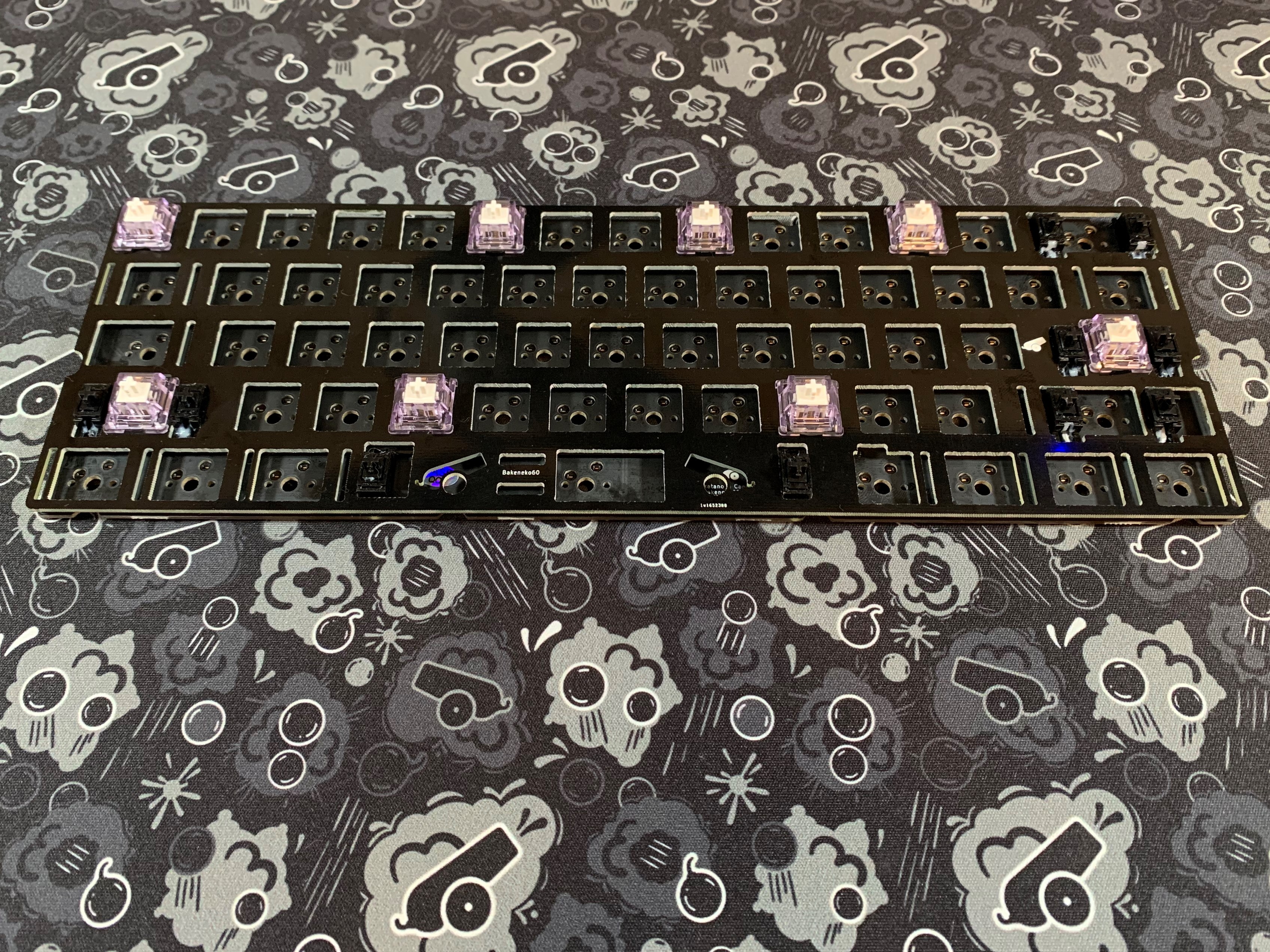
- Now that we know pins are straight and the plate is ontop of the PCB, line up the switch pins to the socket and push in while supporting the socket from the bottom. If the plate slides down on the switch, you can pull it back up, ensuring the switches are clipped in properly.
Note
Be sure to support the hotswap socket from below when installing switches! CannonKeys will not be responsible for damages that occur if this is not done.
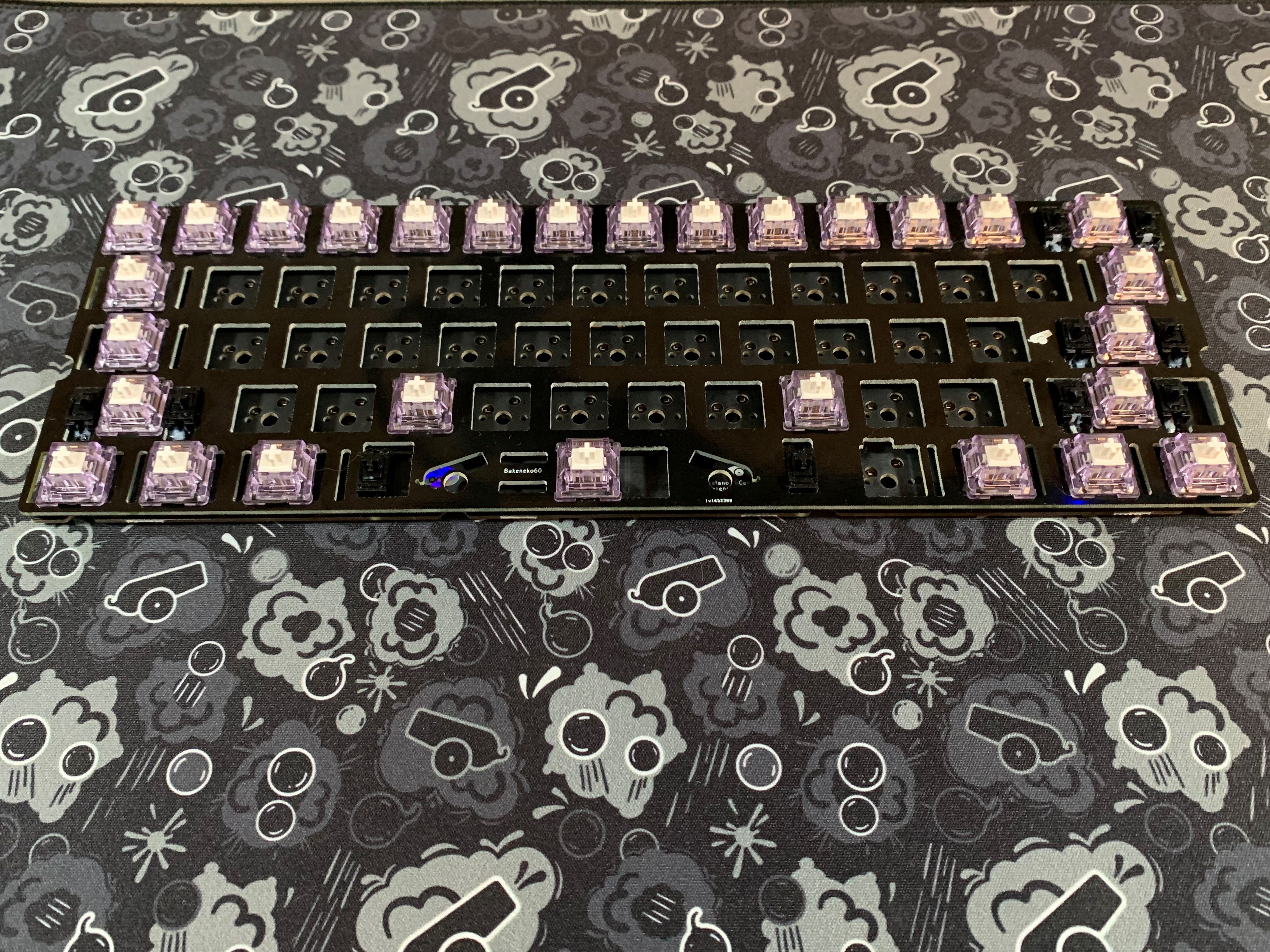
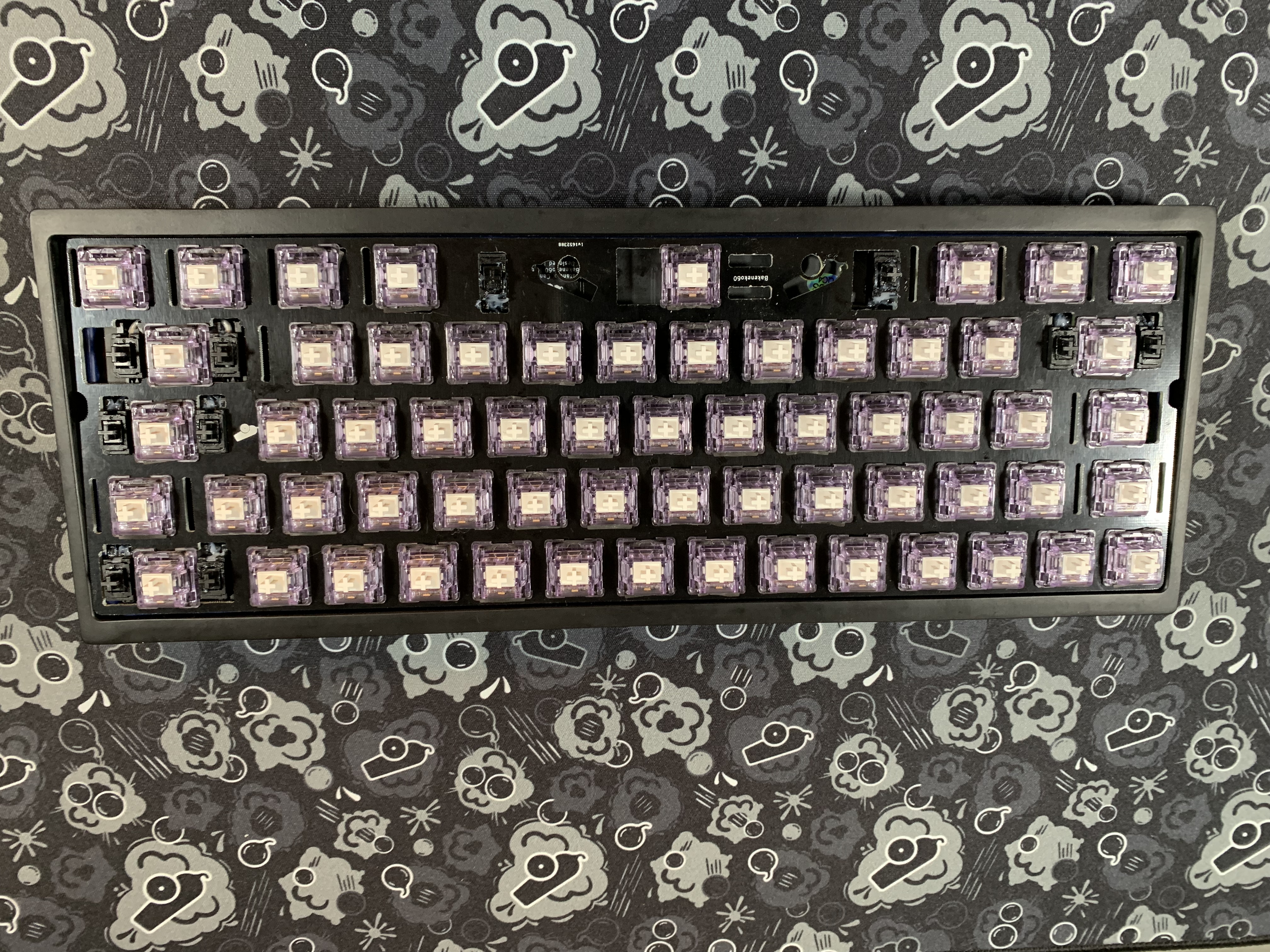
- Now that we have some switches in, go along the border and continue inserting switches. Like the first ones, make sure to support the hotswap sockets, and make sure the plate stays level.
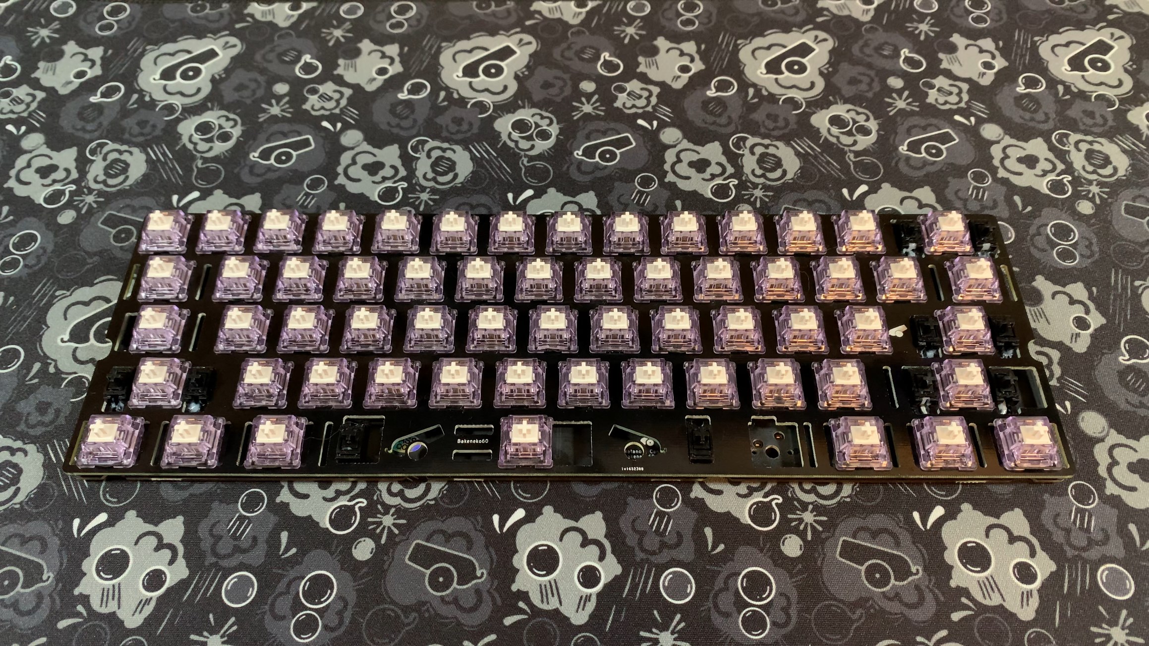
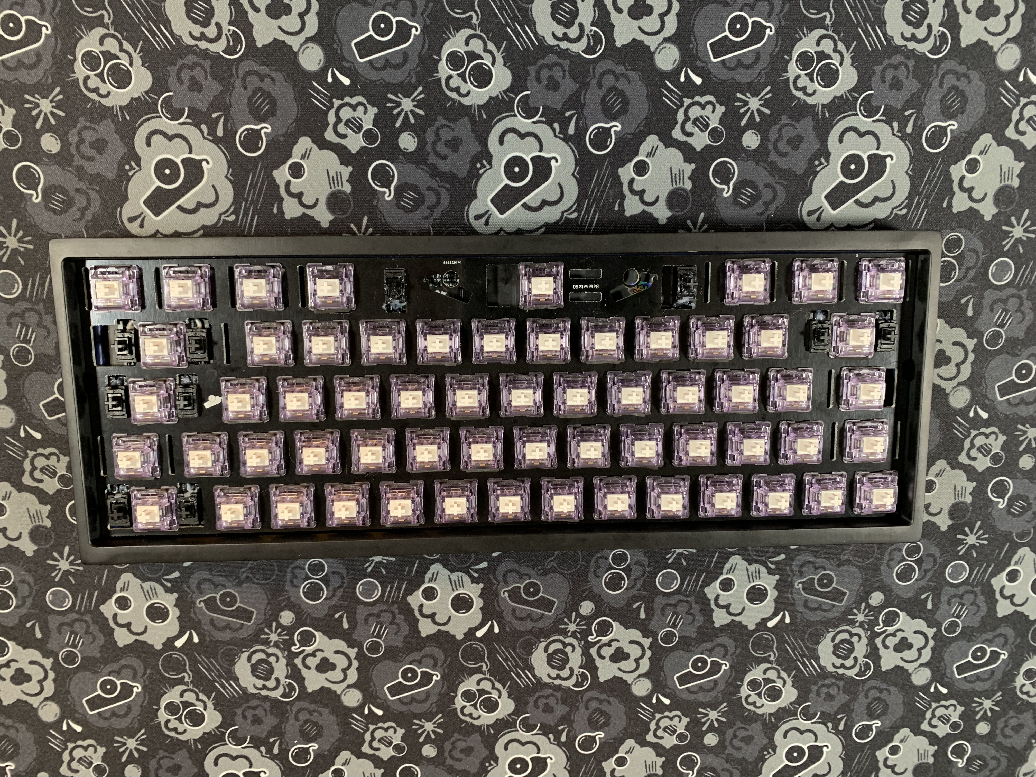
- Finish installing the rest of the switches.
Installing the O-ring
- Now we'll install the O-ring. Follow these visual steps. The o ring is stretchy so don't be afraid to stretch it!
Installing the Battery (BakenekoGO Only)
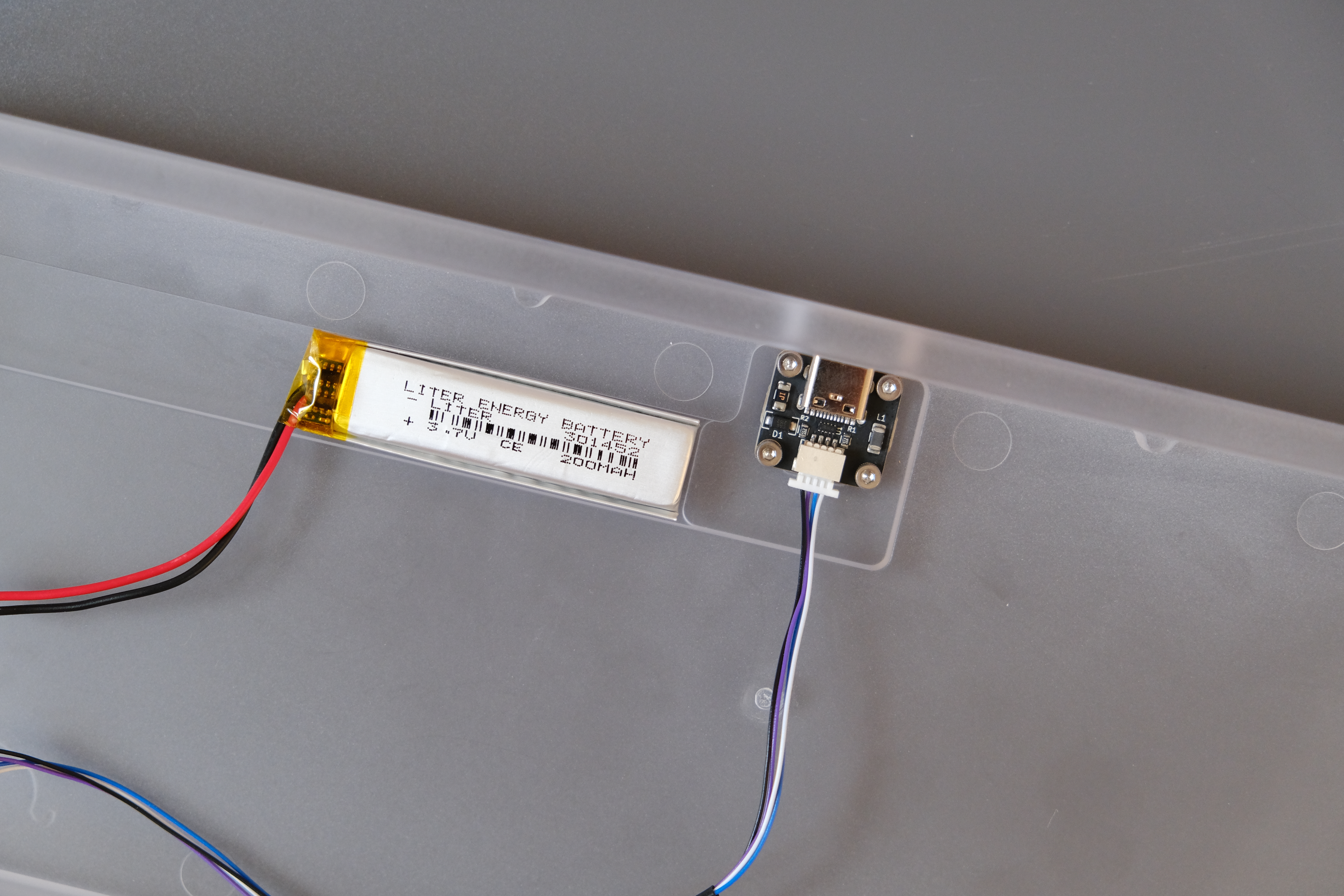
- Using the included double sided tape, install the battery into the case. Try to match the location seen in the image below to avoid interference with PCB components.
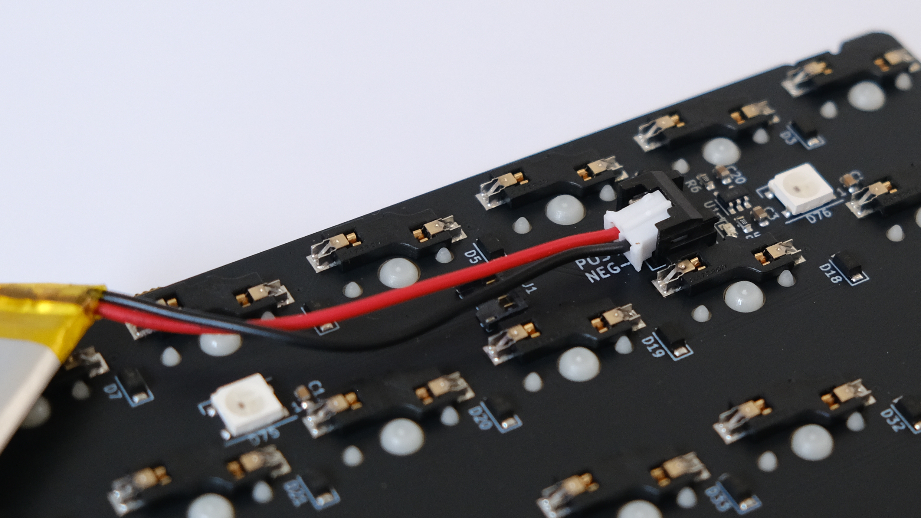
- Insert the battery cable into the header. It is VERY IMPORTANT that the red positive cable is connected to the center positive (POS) pin on the header.
Connecting the PCB
Note
Be careful here! JST connectors can sometimes be delicate, so use caution and be sure not to break it off your PCB! CannonKeys will not be responsible for damages that occur due to forces applied to your JST connector!
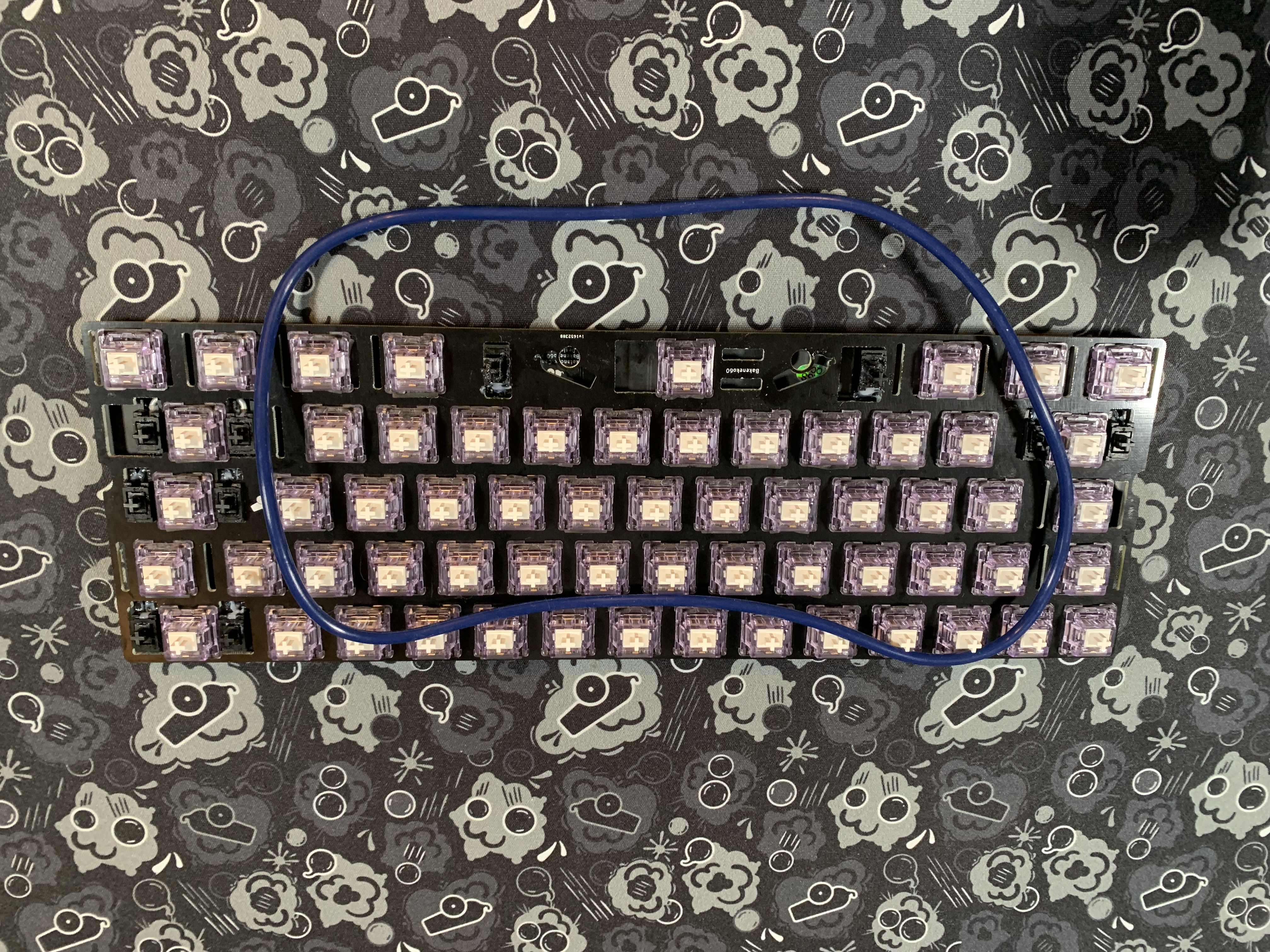
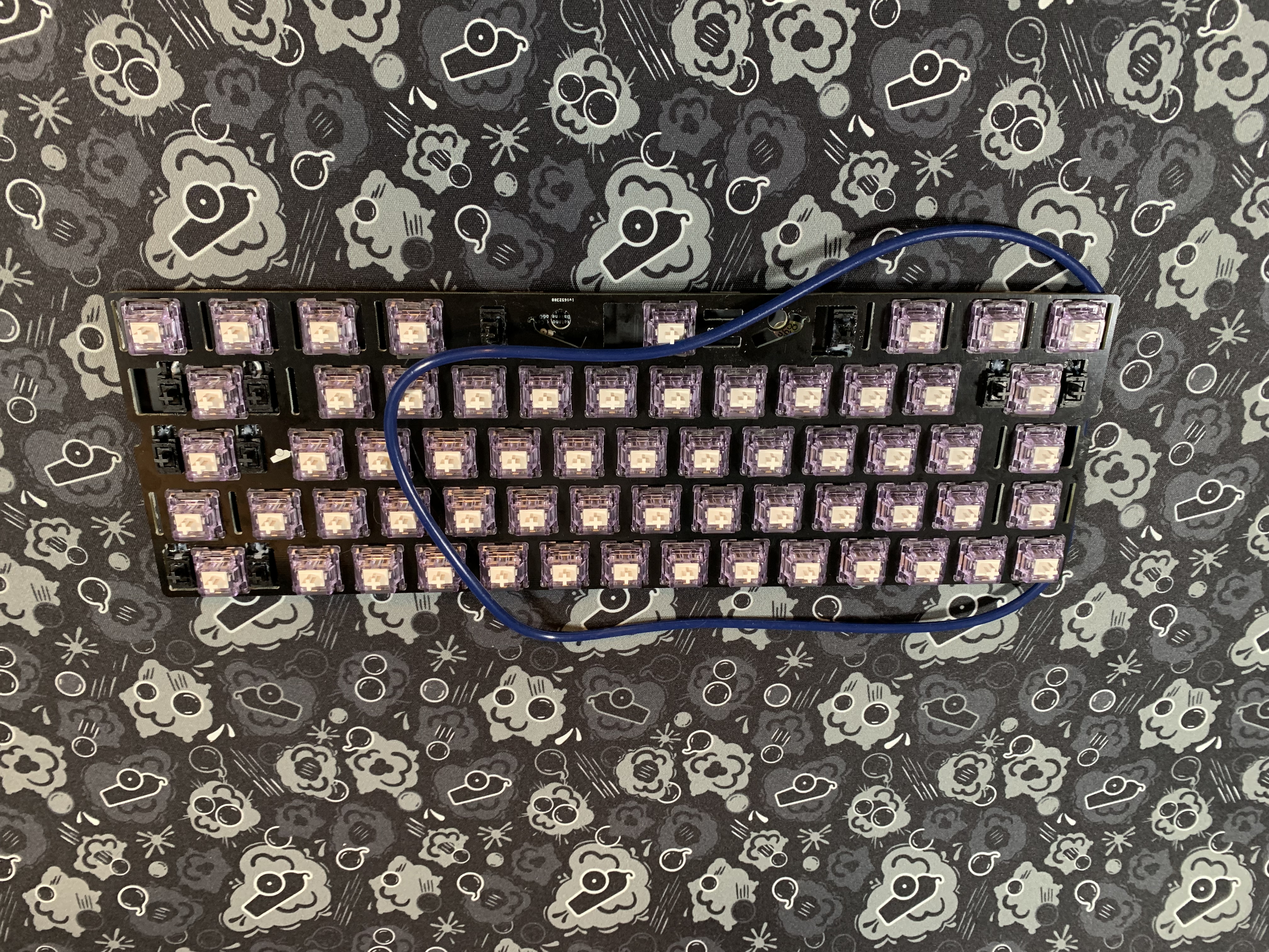
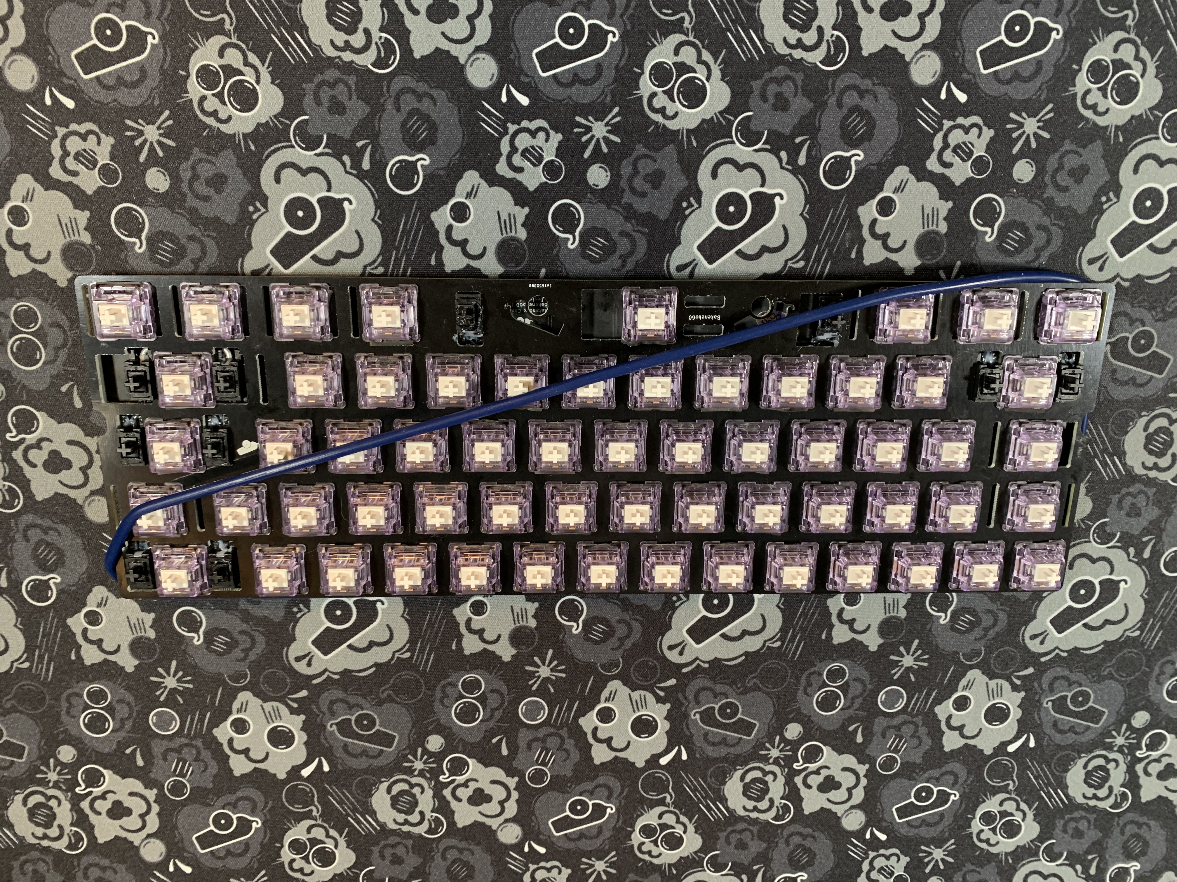
- Now we need to connect the PCB to the daughterboard. Ensuring that the JST or Molex cable is aligned with the connector on the PCB, insert the cable into the connector. If building a BakenekoGO, the battery cable should already be inserted to the PCB.
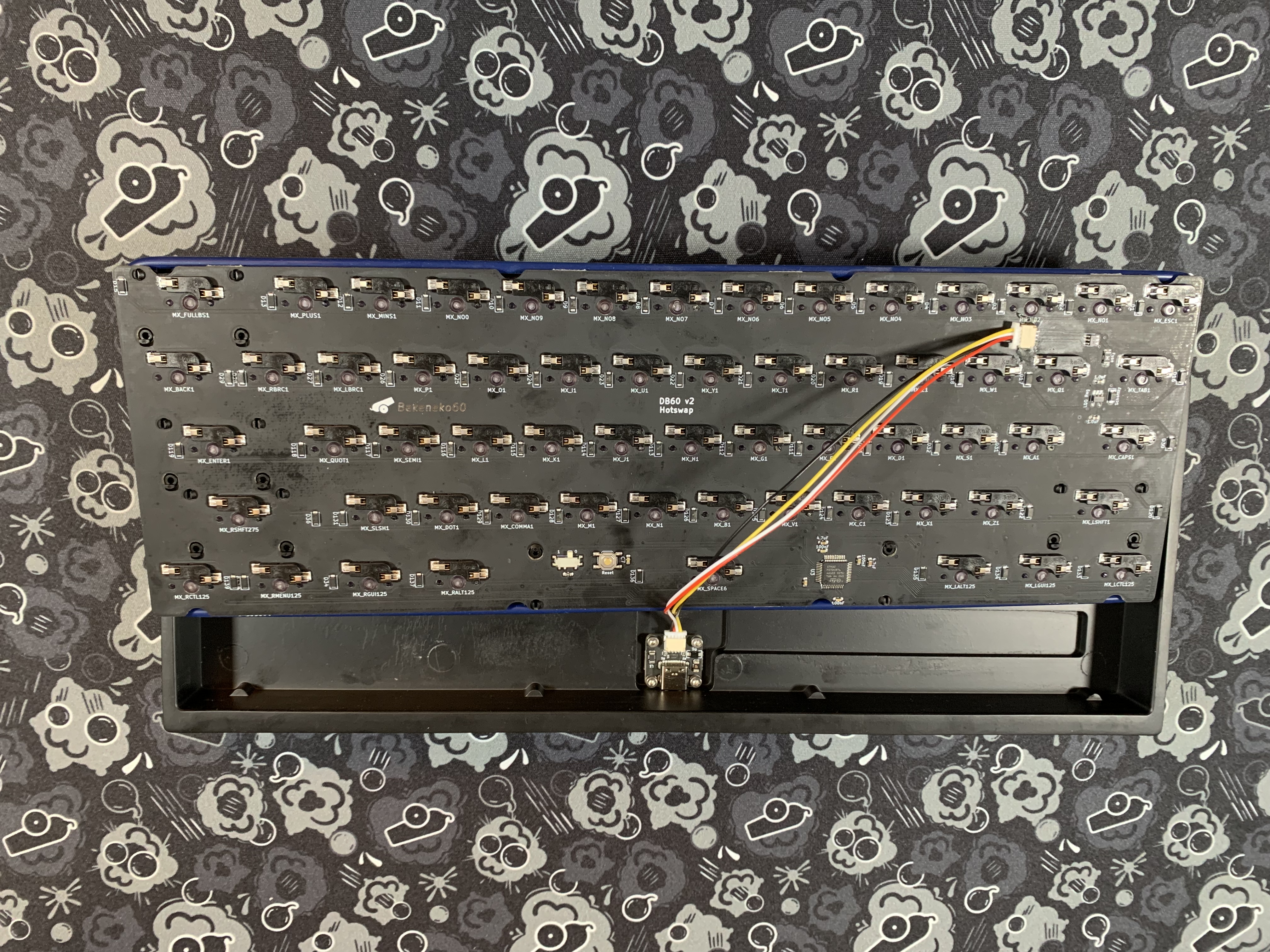
- Flip the PCB over horizontally to orient it properly. Be sure not to cause any stress to the JST/Molex cable or connectors as you do this.
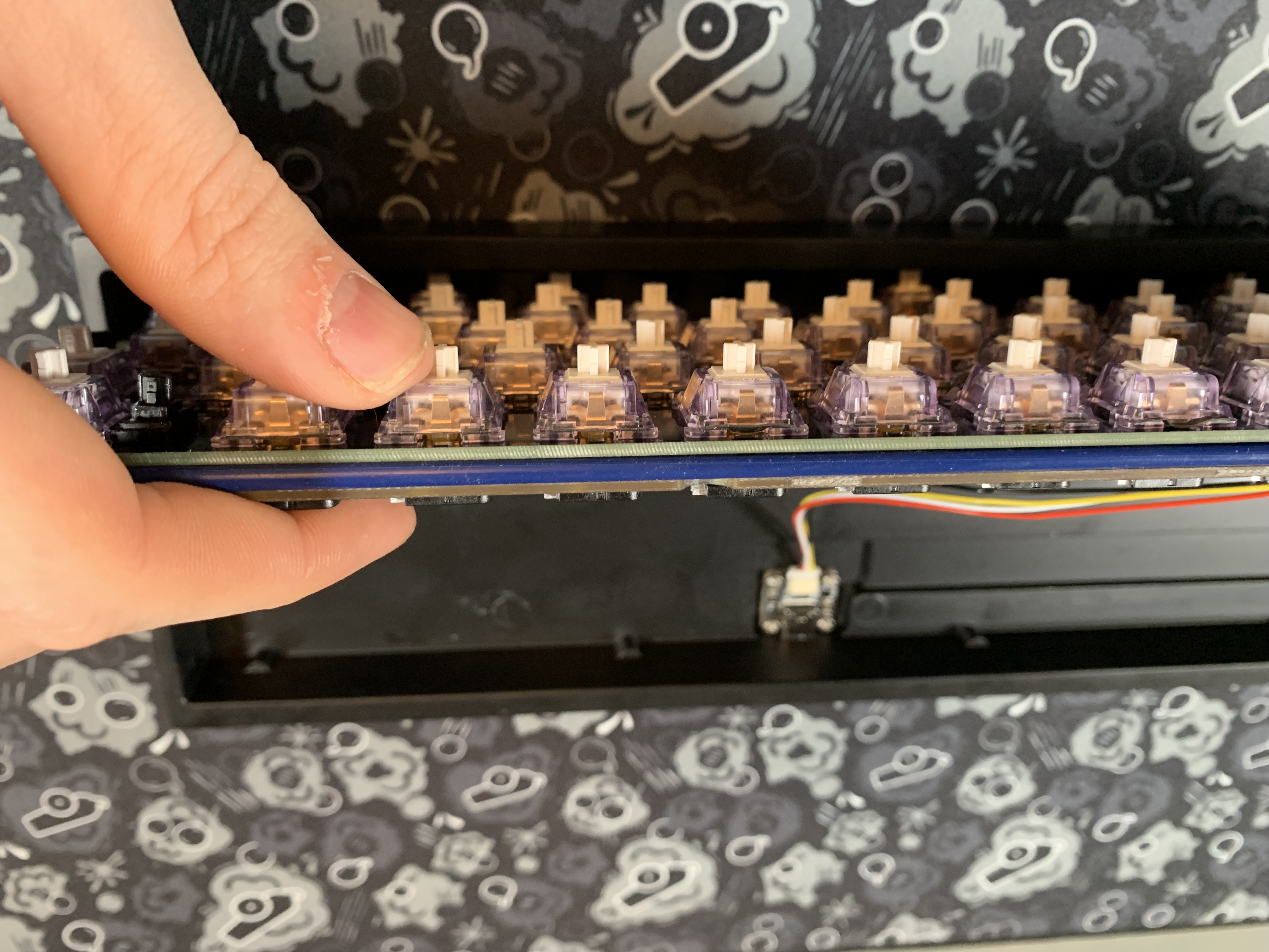
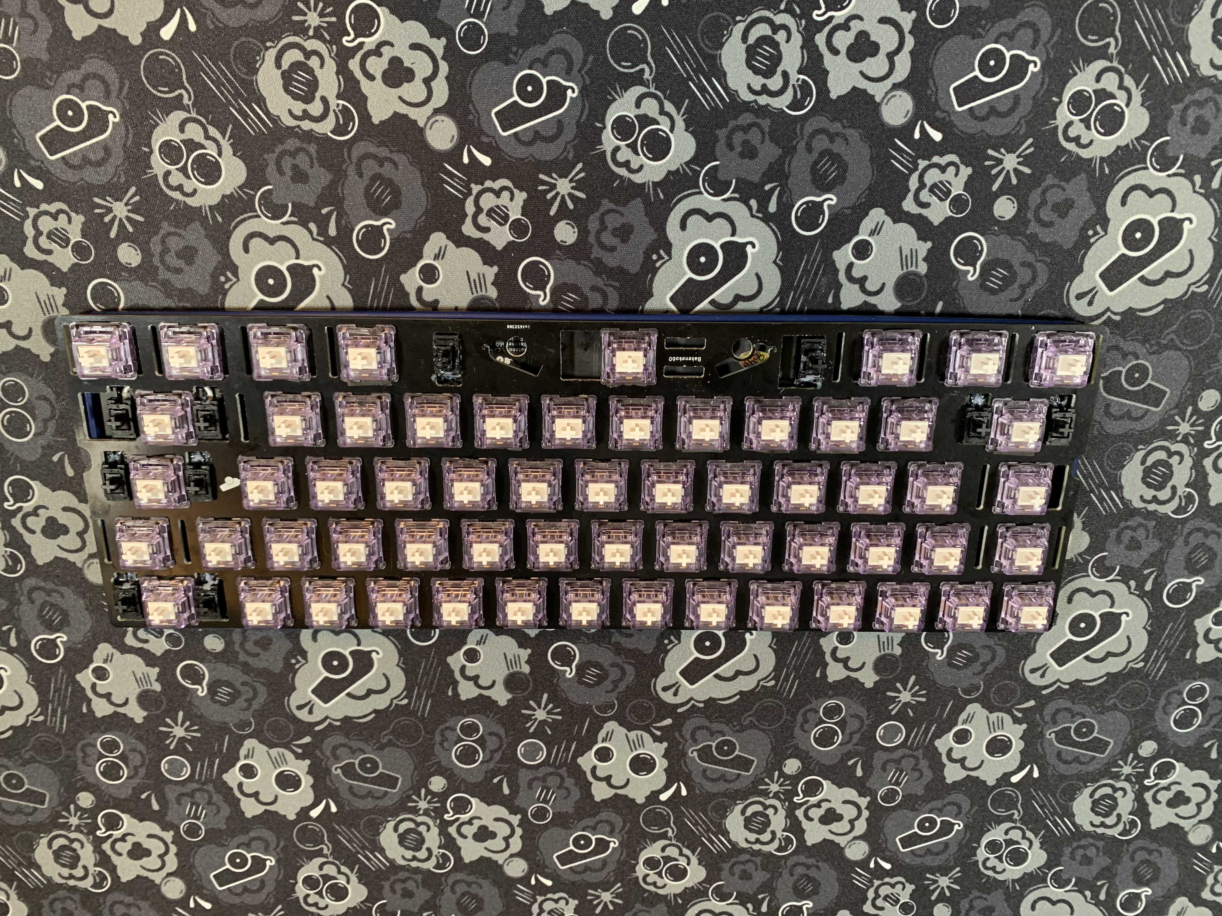
- Tuck the JST/Molex cable under the PCB and lower the assembly.
Final Assembly
- Tuck the o-ring into the inside of the case, paying close attention to the backspace stabilizer (you need to tuck the o-ring in around the entire assembly, but the backspace stabilizer area will be extra tight). You may need to apply some downward pressure in order to do this. The o-ring uses friction to hold the PCB/Plate assembly in.
- Push the PCB/Plate assembly down. You should feel some of the O-ring friction as you do this. It will end up resting on the posts in the case.
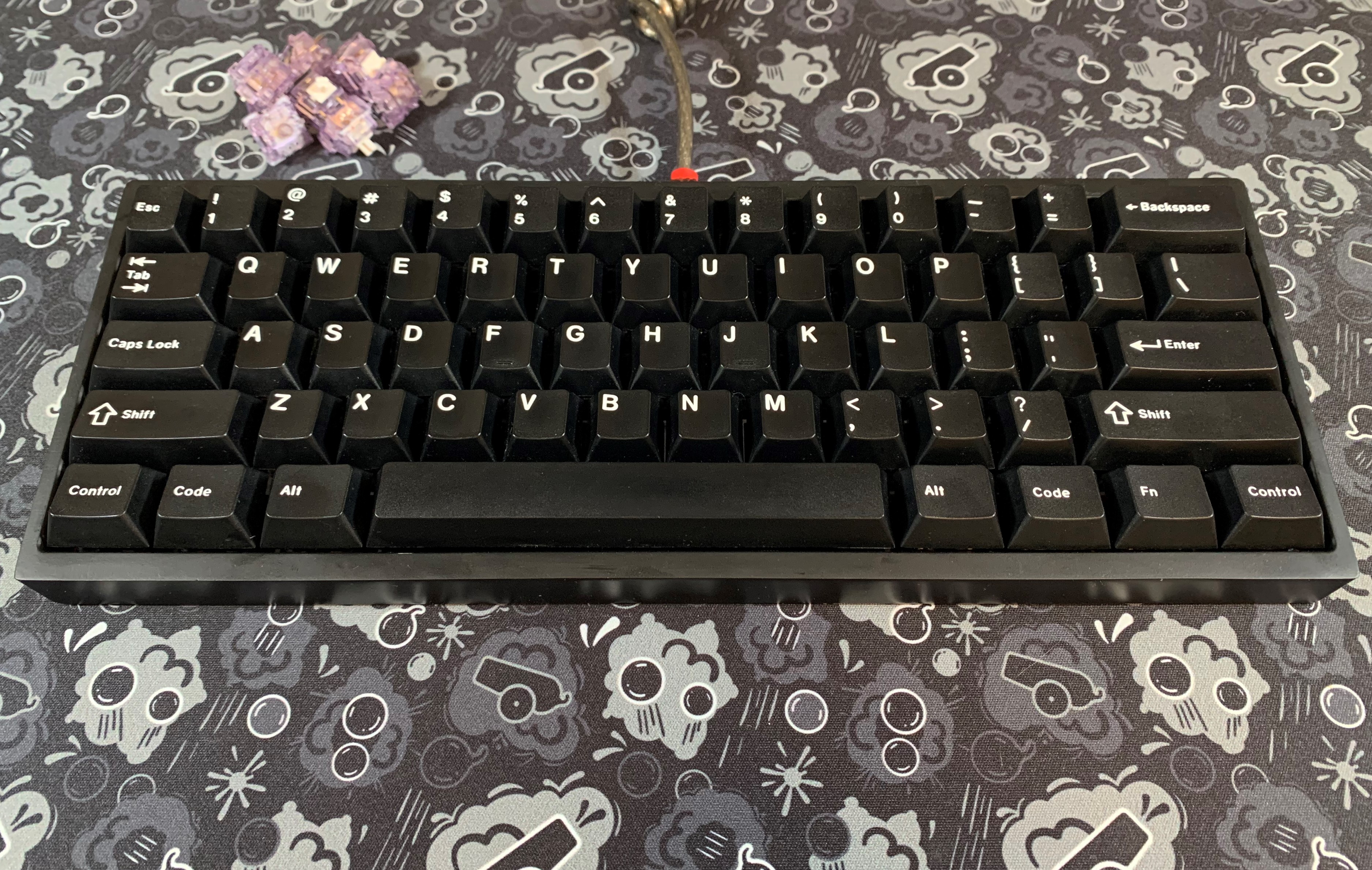
- Add keycaps and ENJOY!
BakenekoGO Remapping, Flashing, and Other Info
We have put together a guide to assist with remapping the keys and flashing your BakenekoGO. We have also created a User Guide that has a bunch of BakenekoGO specific information and a guide on how BT pairing works.
Backspace Fix
For some of the early Bakeneko PCBs, "Delete" is mapped to the "Backspace" key. Here is how to easily fix it using VIA Configurator.
Note
Before applying any of these fixes, make sure you are on the most recent version of VIA. Latest version available here.
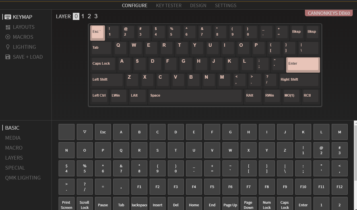
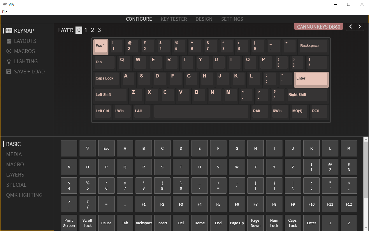
- Open VIA. It will look like this:
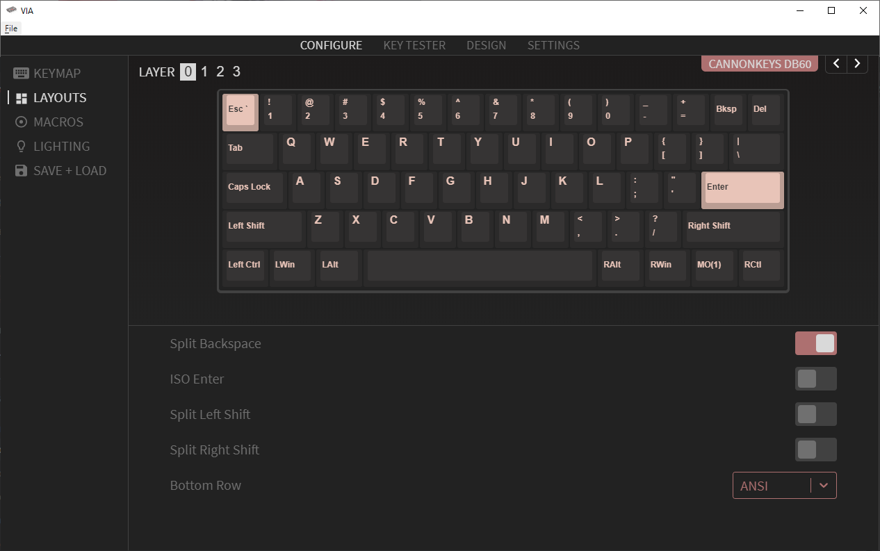
- Using the Layout tab, toggle on "Split Backspace":
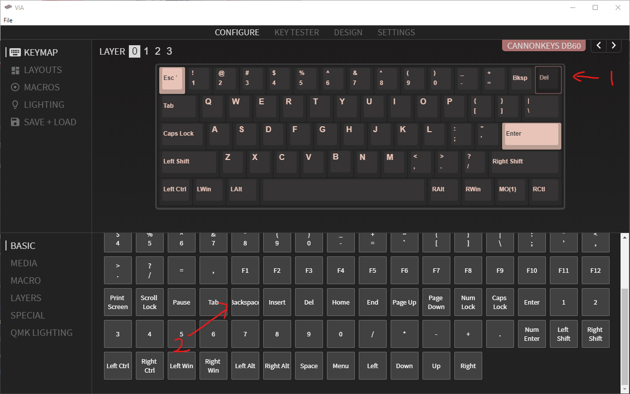
- Go back to the keymap tab, and map "Delete" to "Backspace"
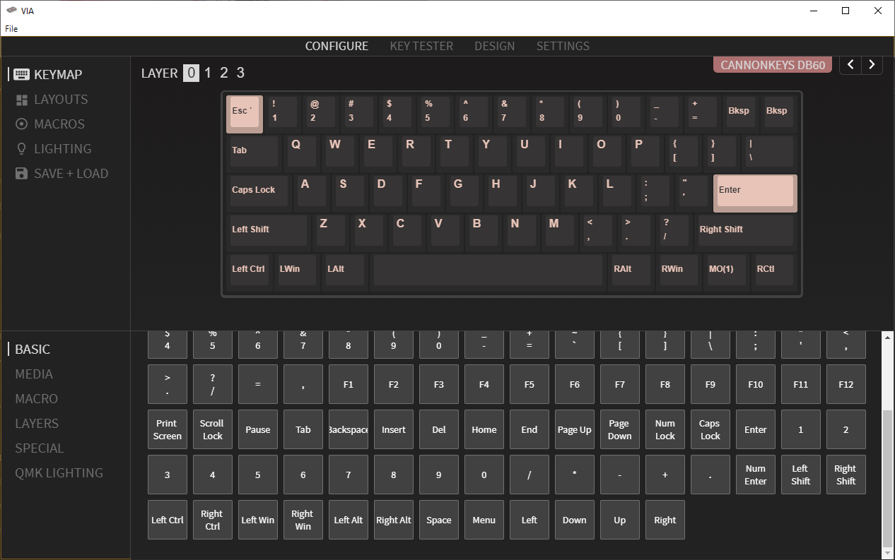
- Backspace is now fixed!
Spacebar Fix
For some of the Bakeneko PCBs (db60), there is an issue in rebinding the spacebar within VIA. Here is the fix for the issue.
- Download the .json
- Open the file in a text editor, and change every occurrence of
4,5to4,6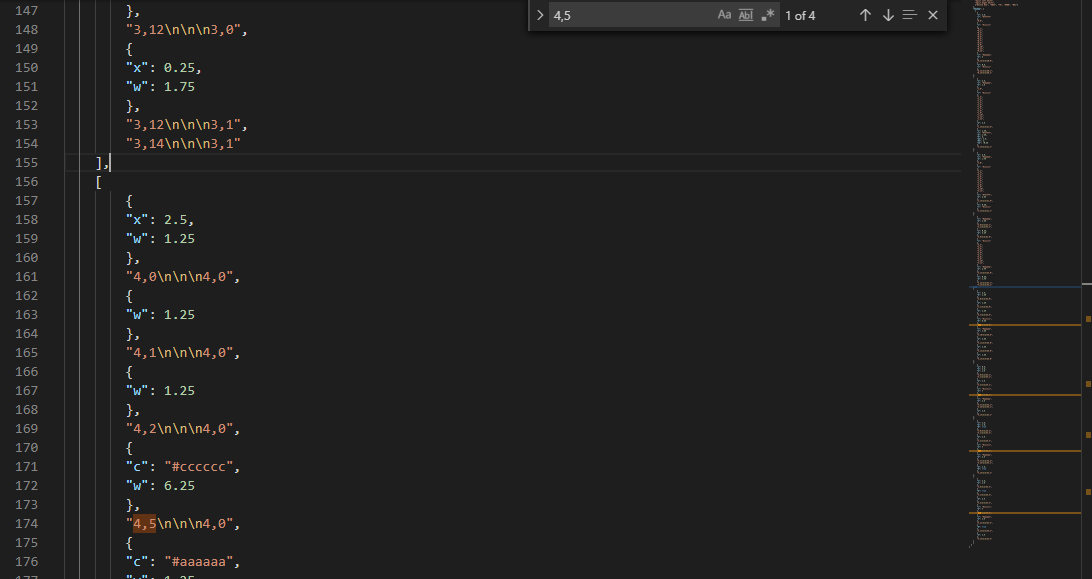
- Save the document, and open Via.
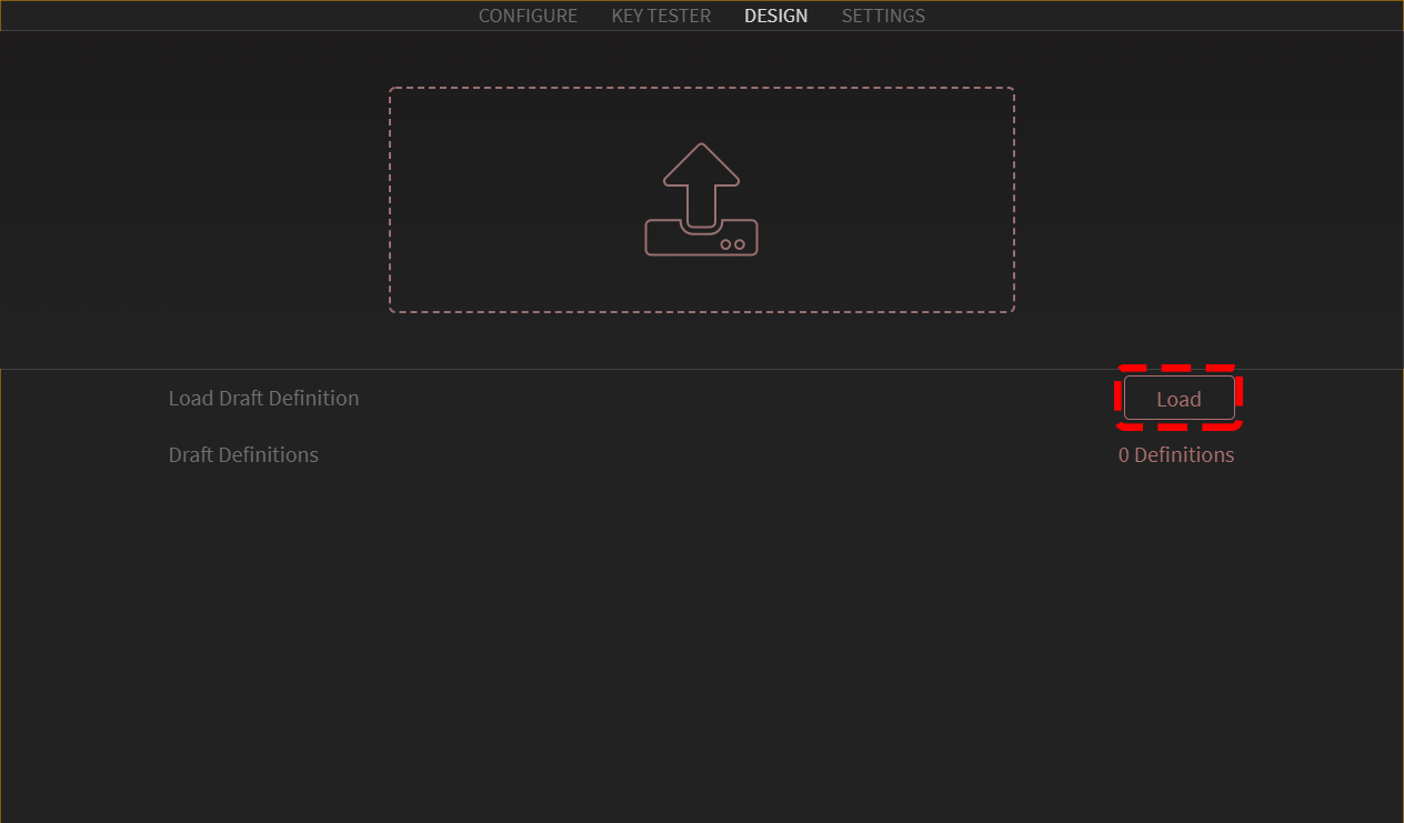
- Once in via, go to the design tab. Click the load button, and open the .json you just saved.
Note
If you do not see a design tab, go to the settings tab and toggle it.
 5. Once loaded, your screen should show the keyboard matrix like this.
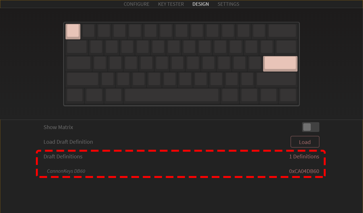 6. Once that is done, click on the configurator tab on the top left of VIA. You should now be able to edit your keymap as you wish.