Build Guide for the Practice60/65 and Ortho48/60/75
These three boards are all Bluepill based. While the guide photos were taken with the Practice60, the steps still apply for the Ortho60 and Ortho48 as well.
Any differences will be called out inside this guide.
Note
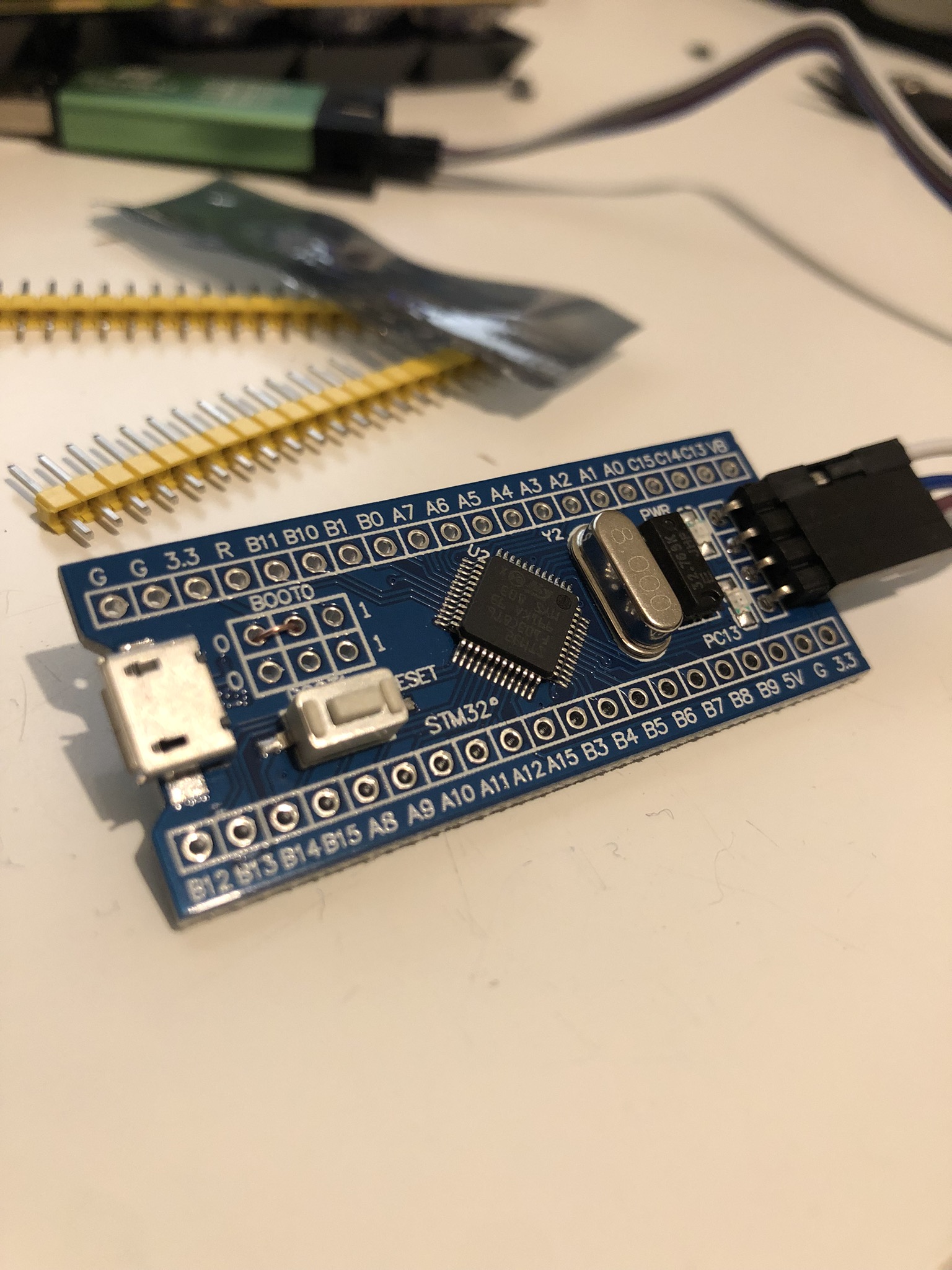
Before starting this build, you should flash your Blue Pill using a Micro USB cable, and also test your Blue Pill
Note
Do not plug in both the MicroUSB port on the BluePill and the Mini USB port on your keyboard kit at the same time. This could cause irreparable damage to either the kit, or your computer, so remember - one at a time!
Setup
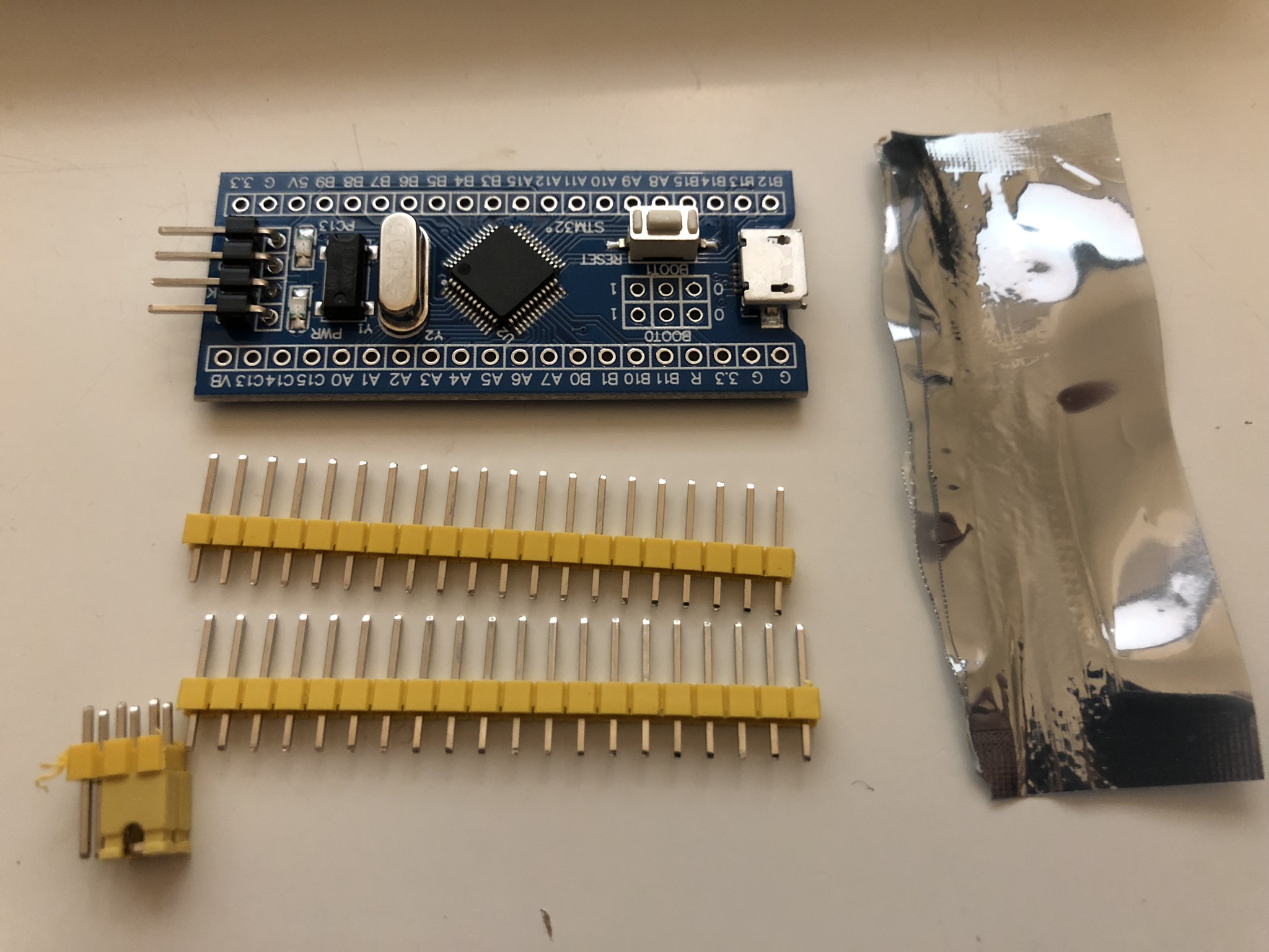
- Starting Kit:
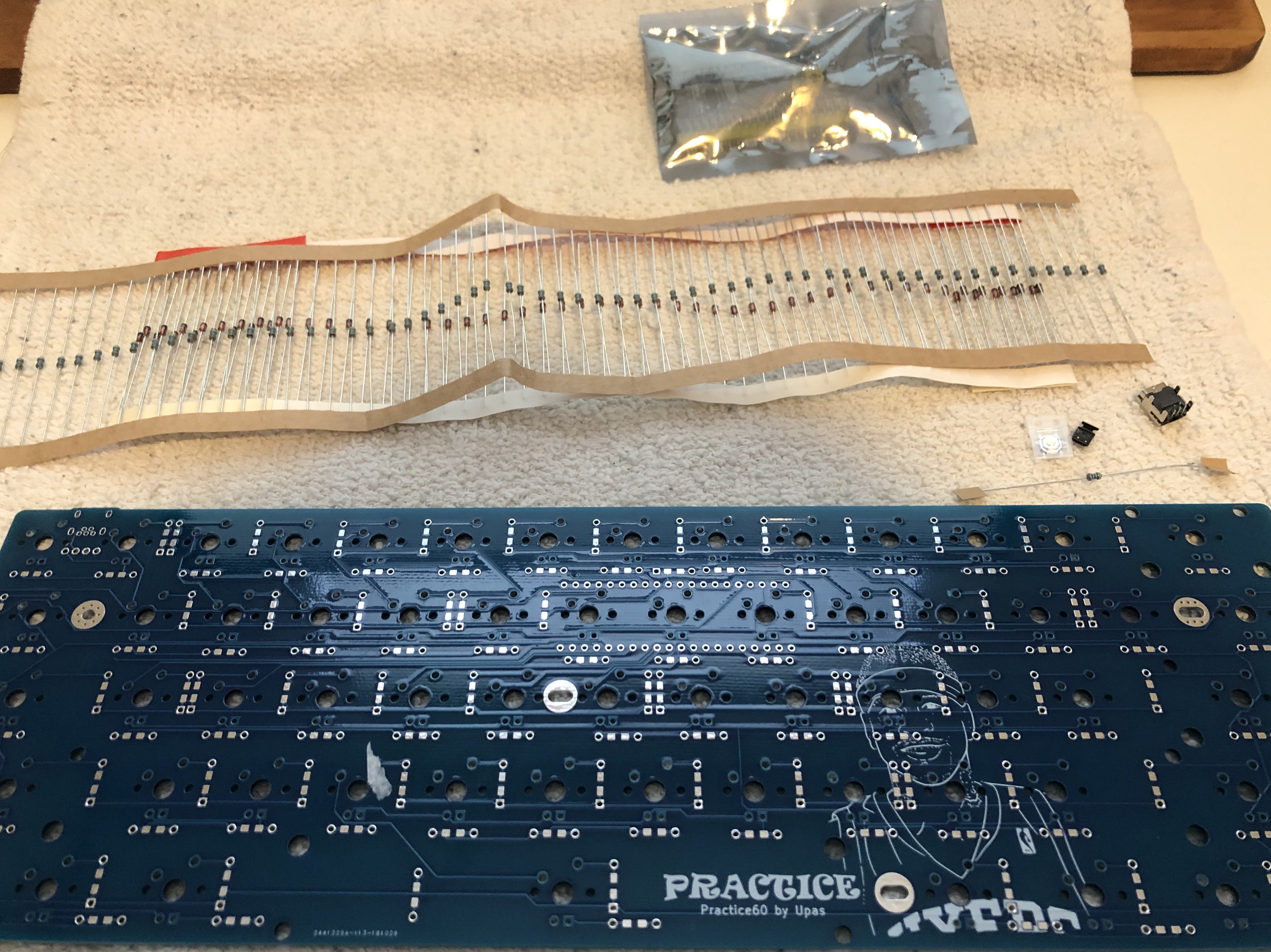
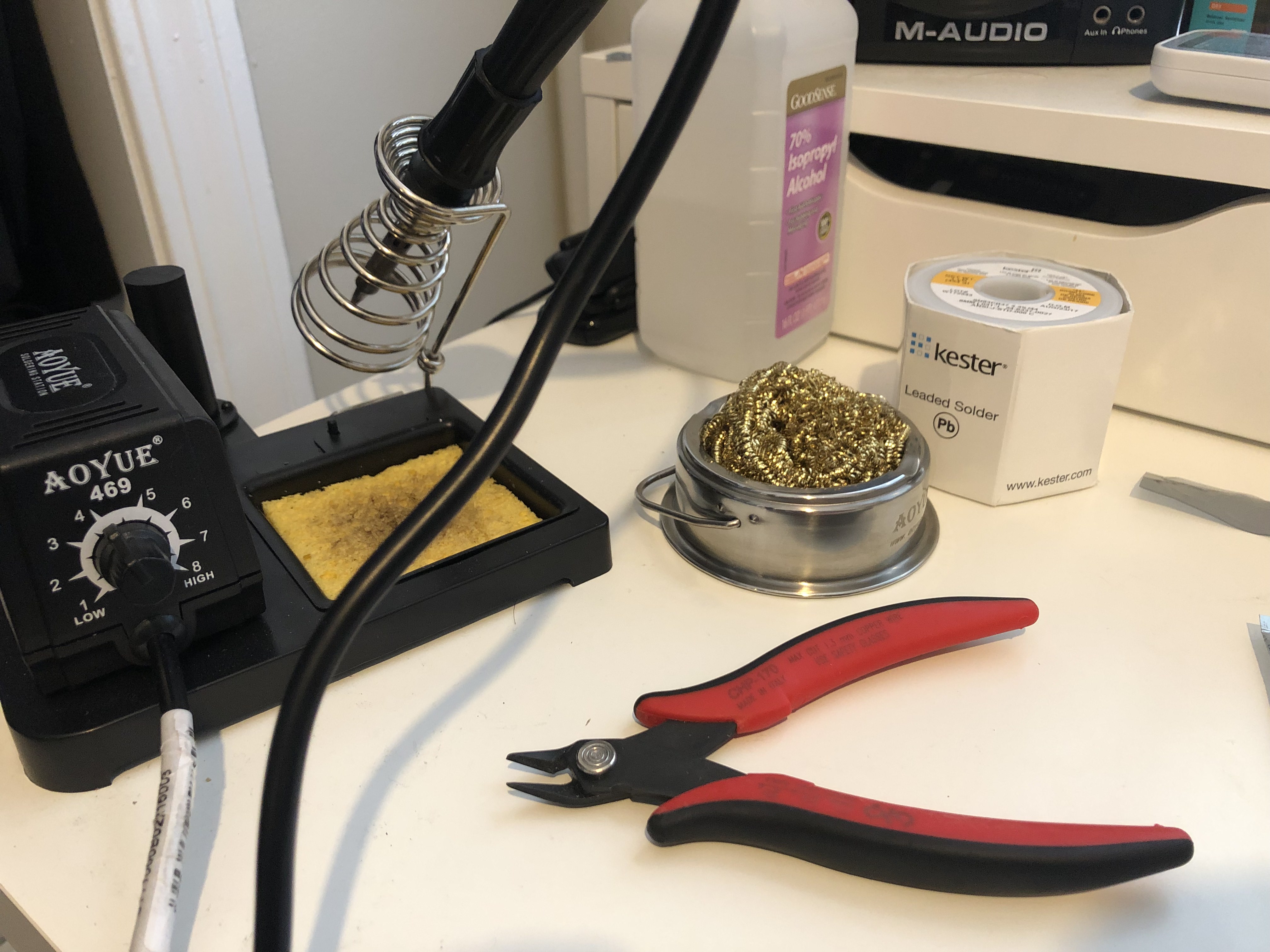
- Tools:
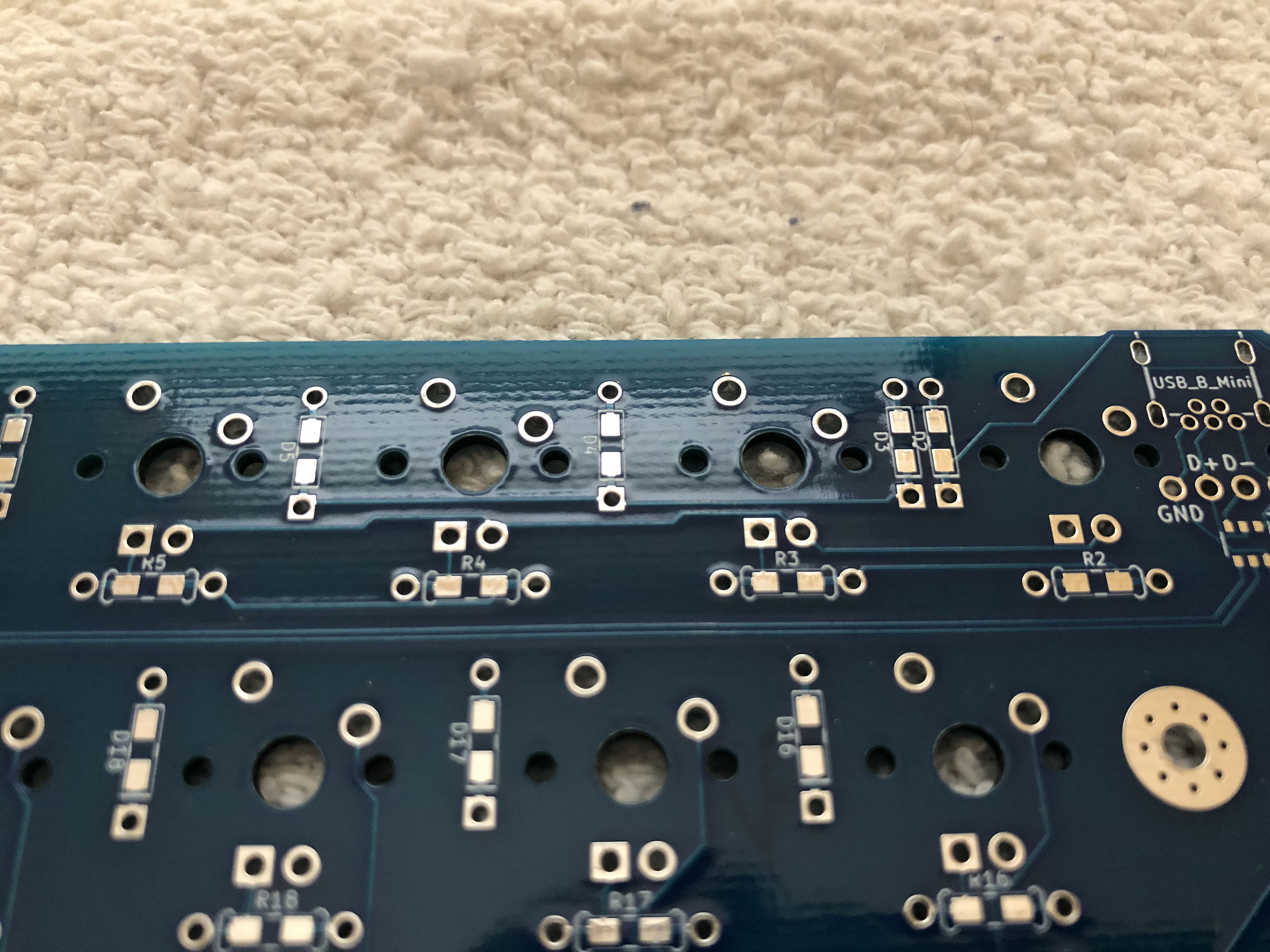
Diodes
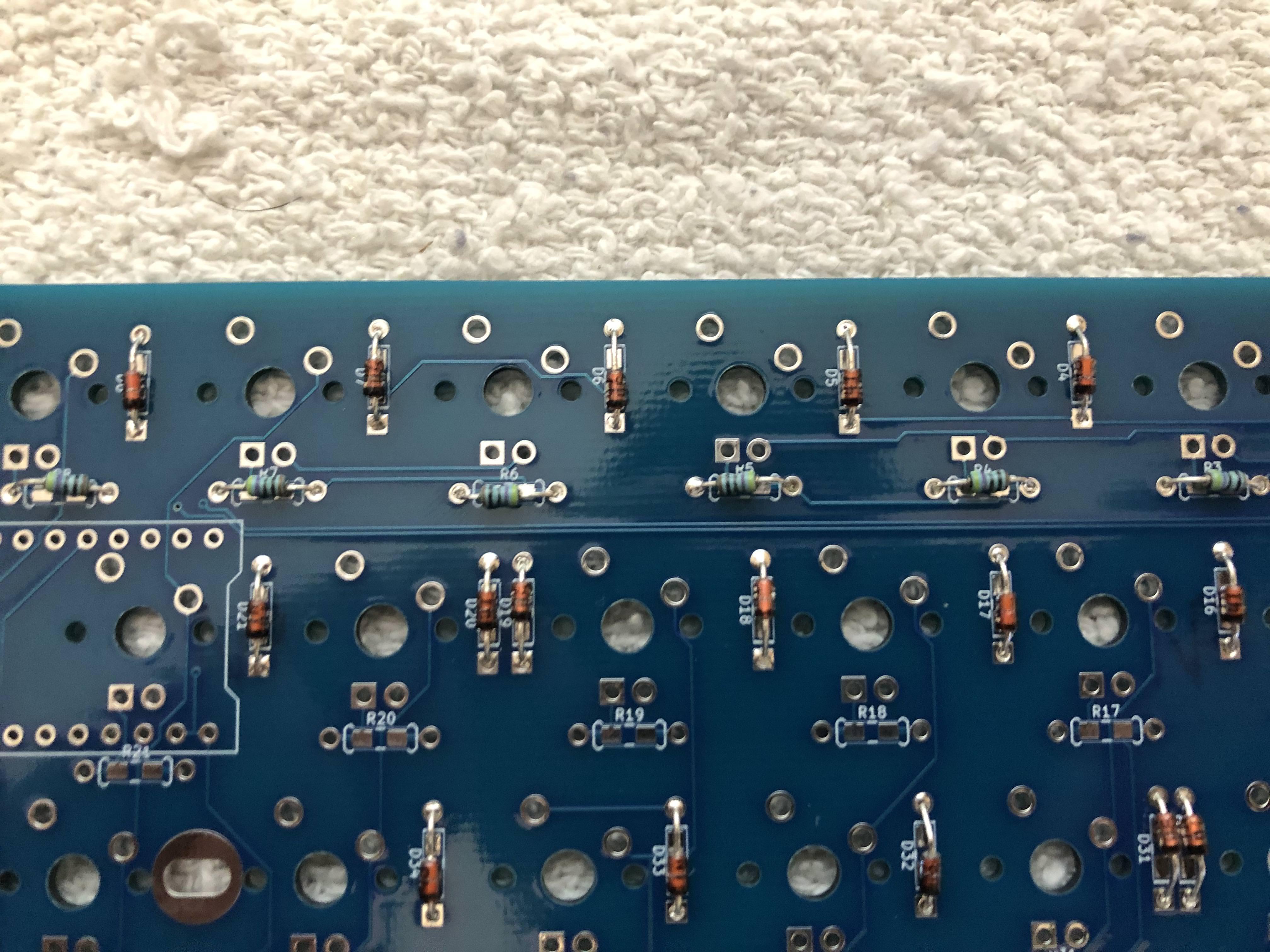
- First step - diodes. They are all marked with "D" on the back of the PCB. I suggest soldering them on the back of the PCB.
- Bend your diodes around your finger for easy insertion.
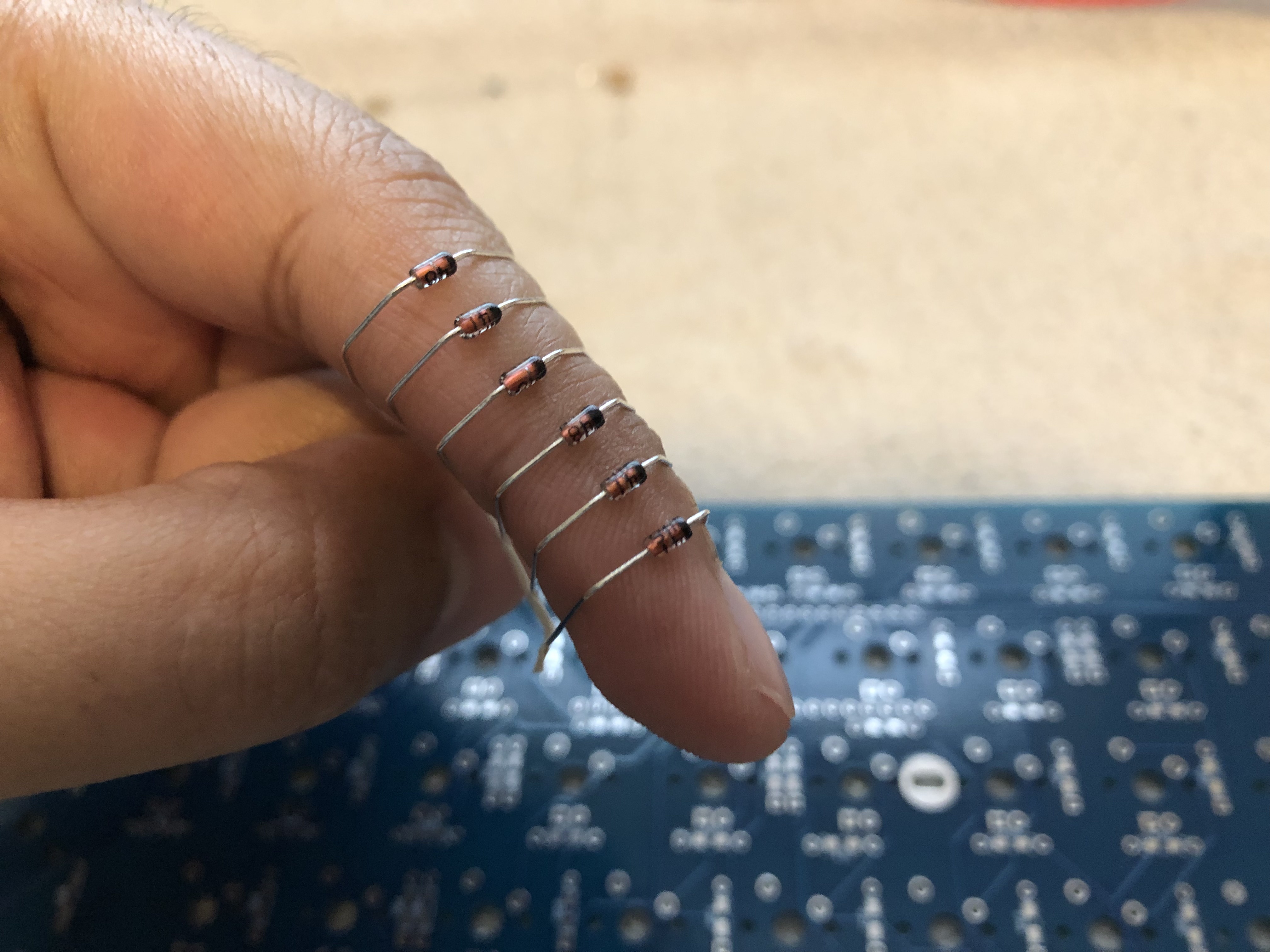
- The black band on the diode should face the SQUARE pad - on all CannonKeys PCBs it means pointing down.
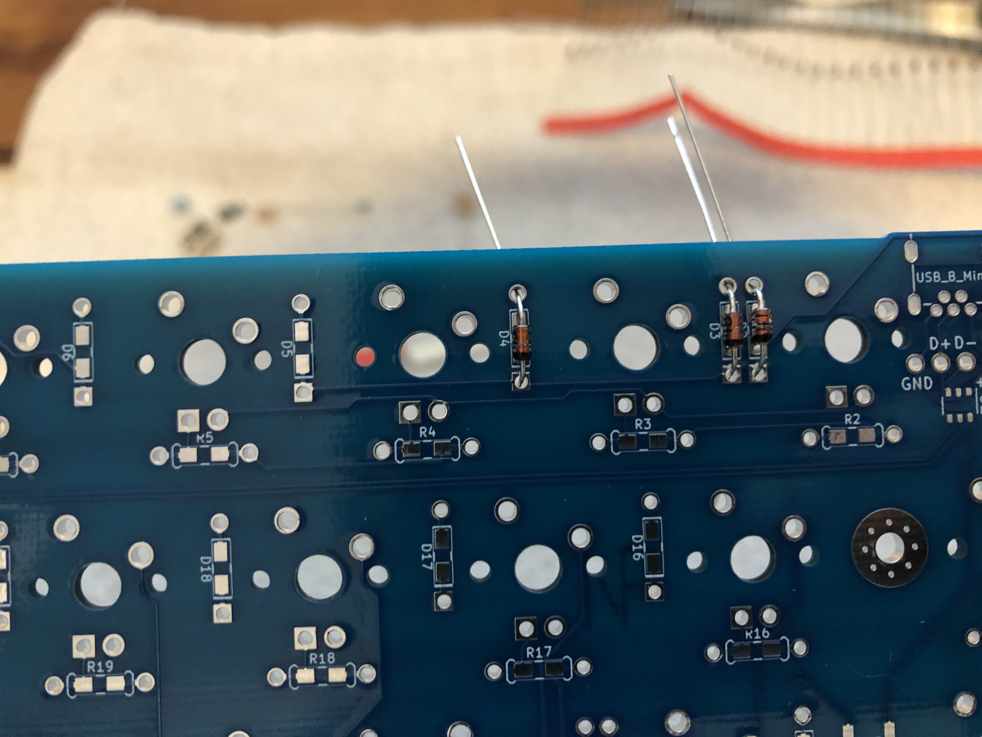
- Solder the diodes once they've been inserted
- Then use your flush cutters to cut the legs. Make sure you save them for a later step!
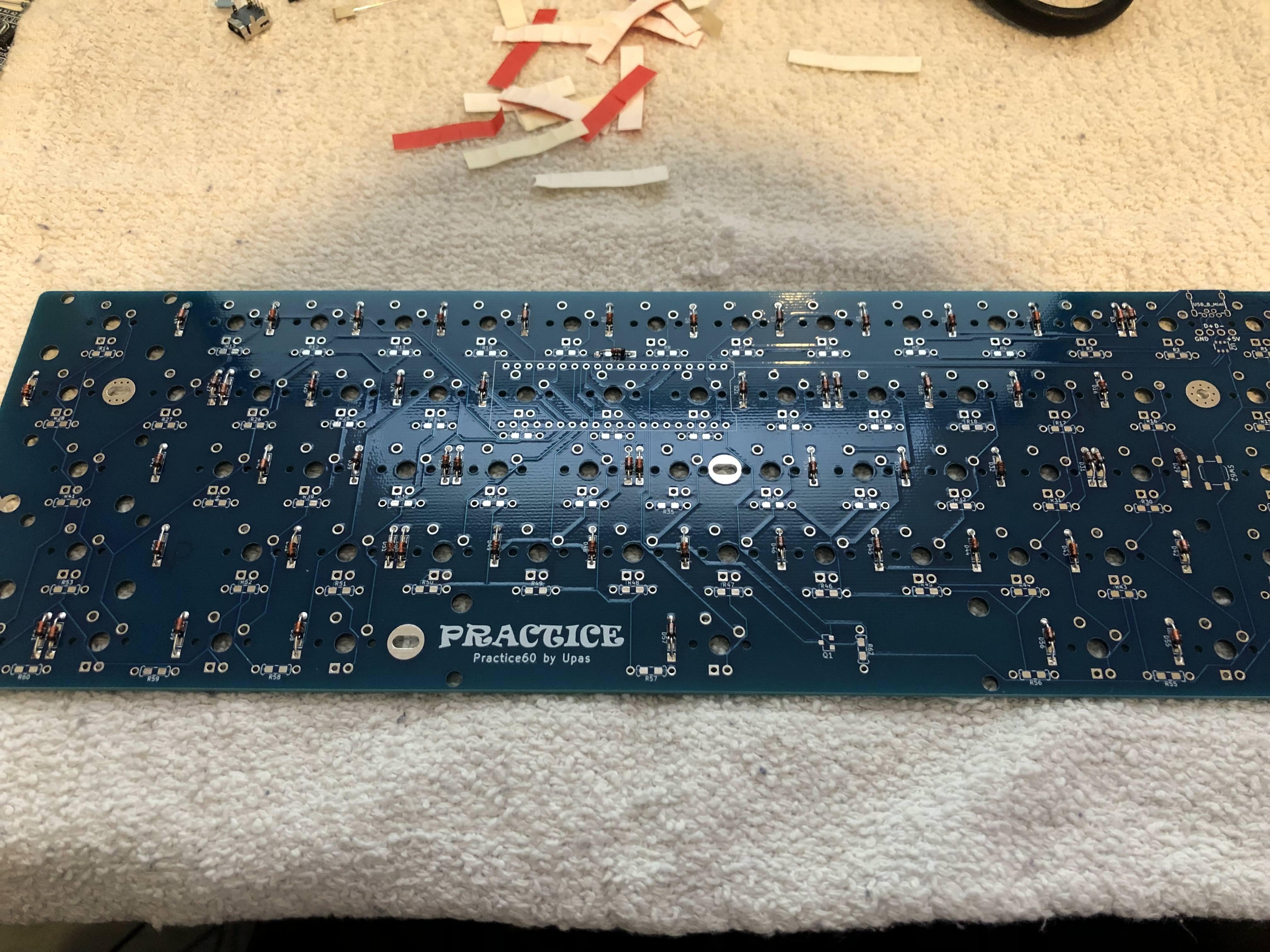
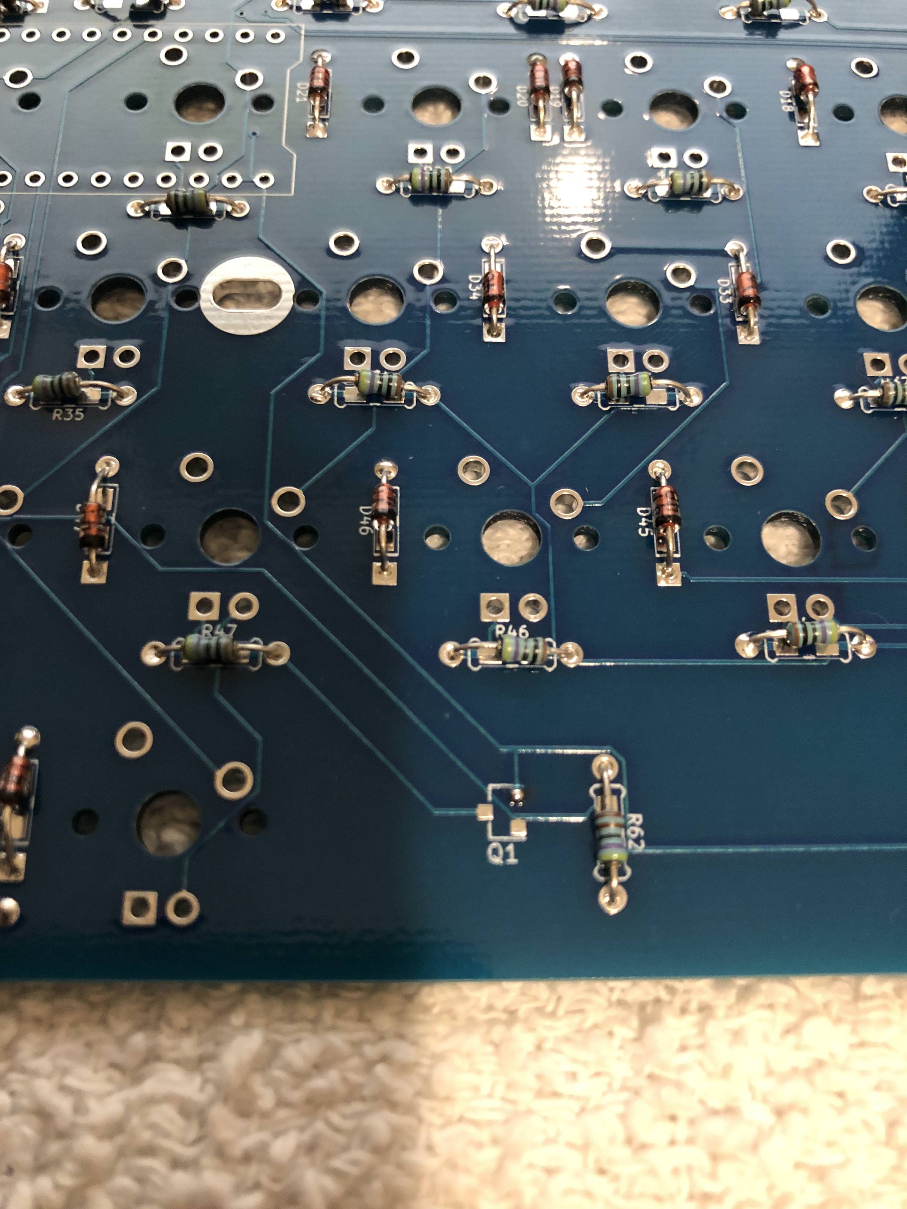
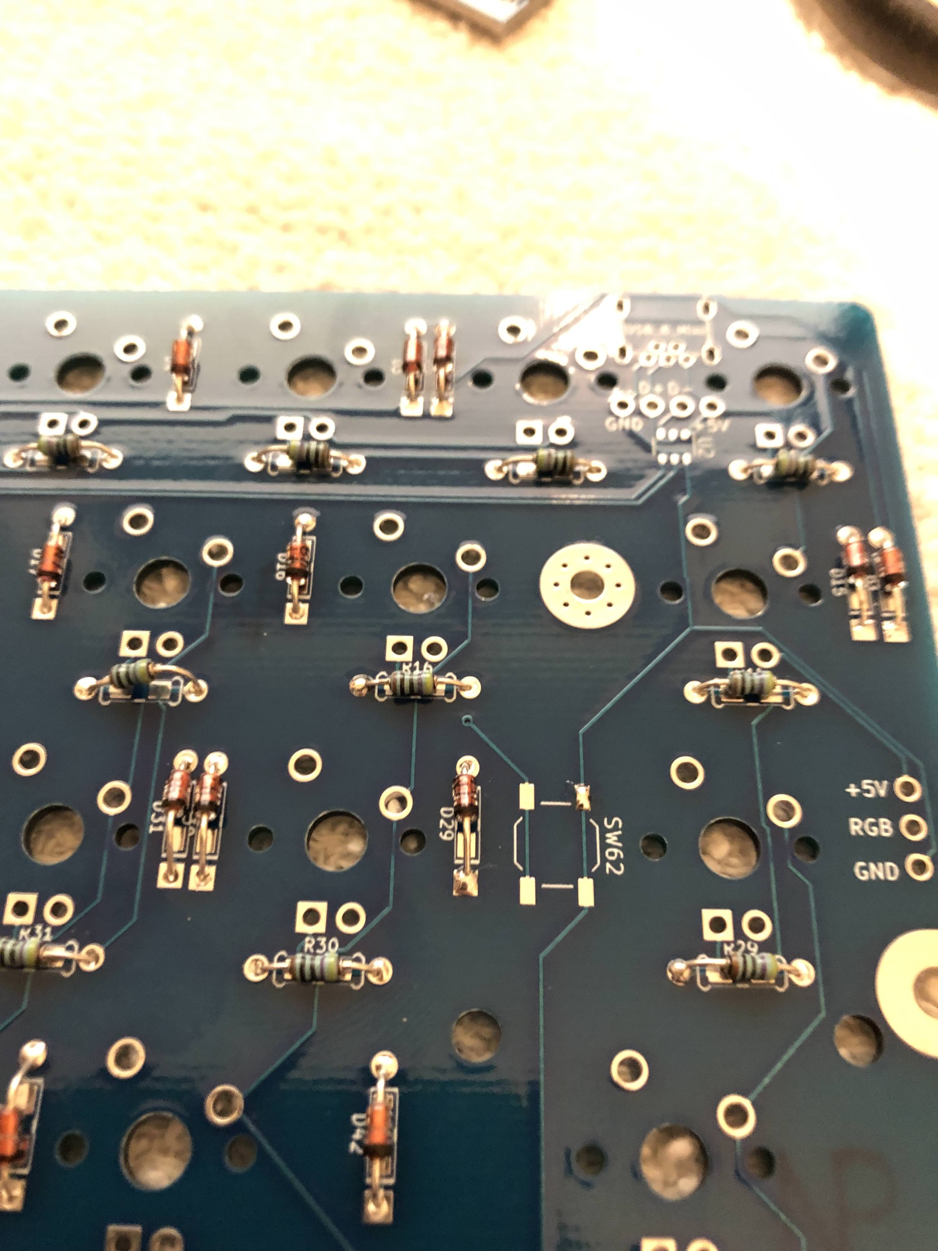
- Finish soldering all the diodes. At the end, your board should look like this:
MOSFET for Backlighting (Optional)
Optional
These next few steps coming up are optional, and only necessary if you want to add per-key LED backlighting to your board. These steps could be difficult as they require soldering SMD parts. Please watch this video for a video guide! If you want to skip, you can jump to the next mandatory section
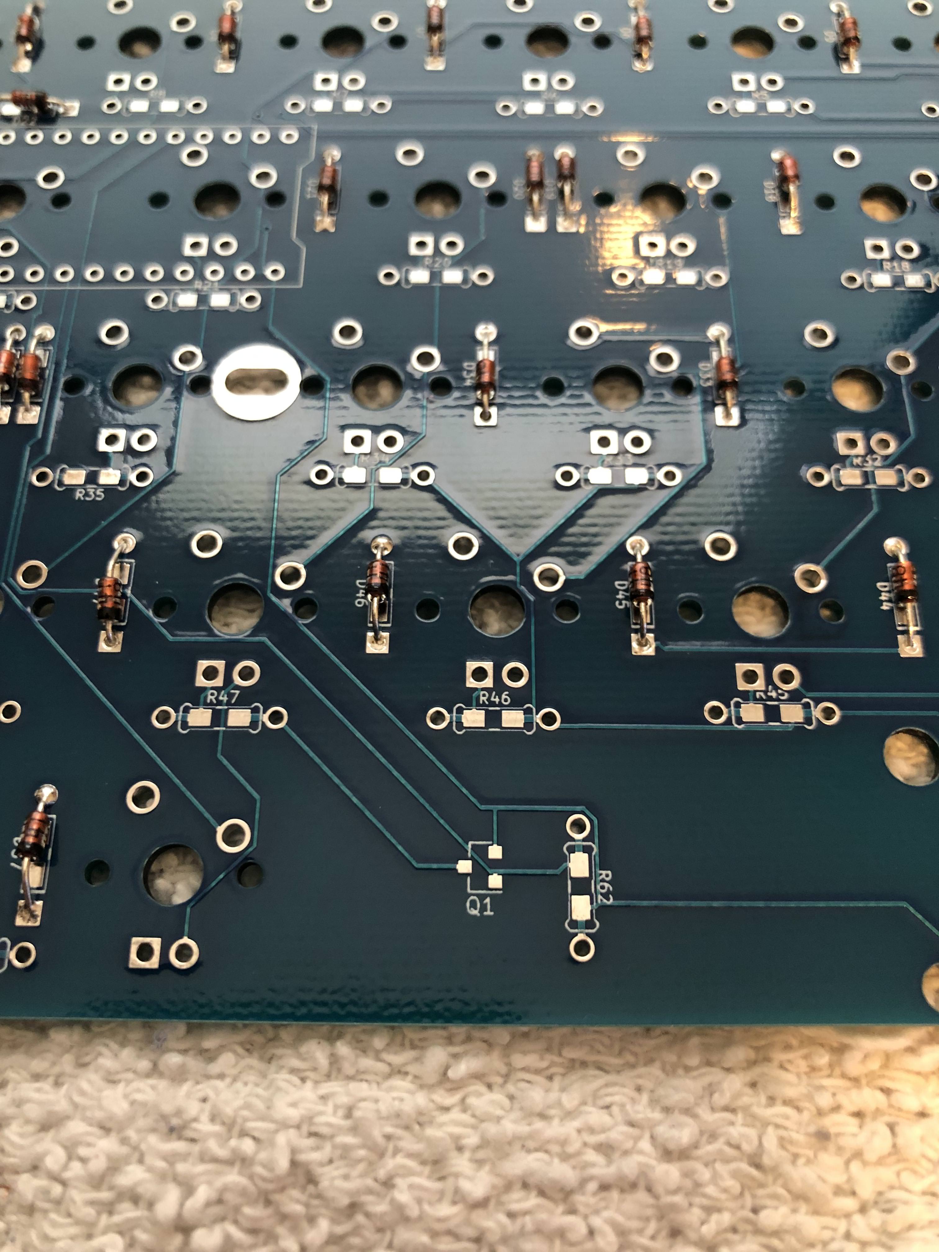
- Now, if we want LED backlighting, we need to solder the MOSFET on Q1. Put a little solder on one of the pads.
-
Using tweezers, hold the MOSFET to the pad, oriented the correct way. Use a soldering iron to make the dot of solder you added heat up. and solder the MOSFET to the board.
Mandatory
After this block, steps are mandatory unless otherwise noted!
Resistors for Backlighting (Optional)
Optional
This step is optional, and only necessary if you want to add per-key LED backlighting to your board. If you want to skip this, you can jump to the next mandatory section
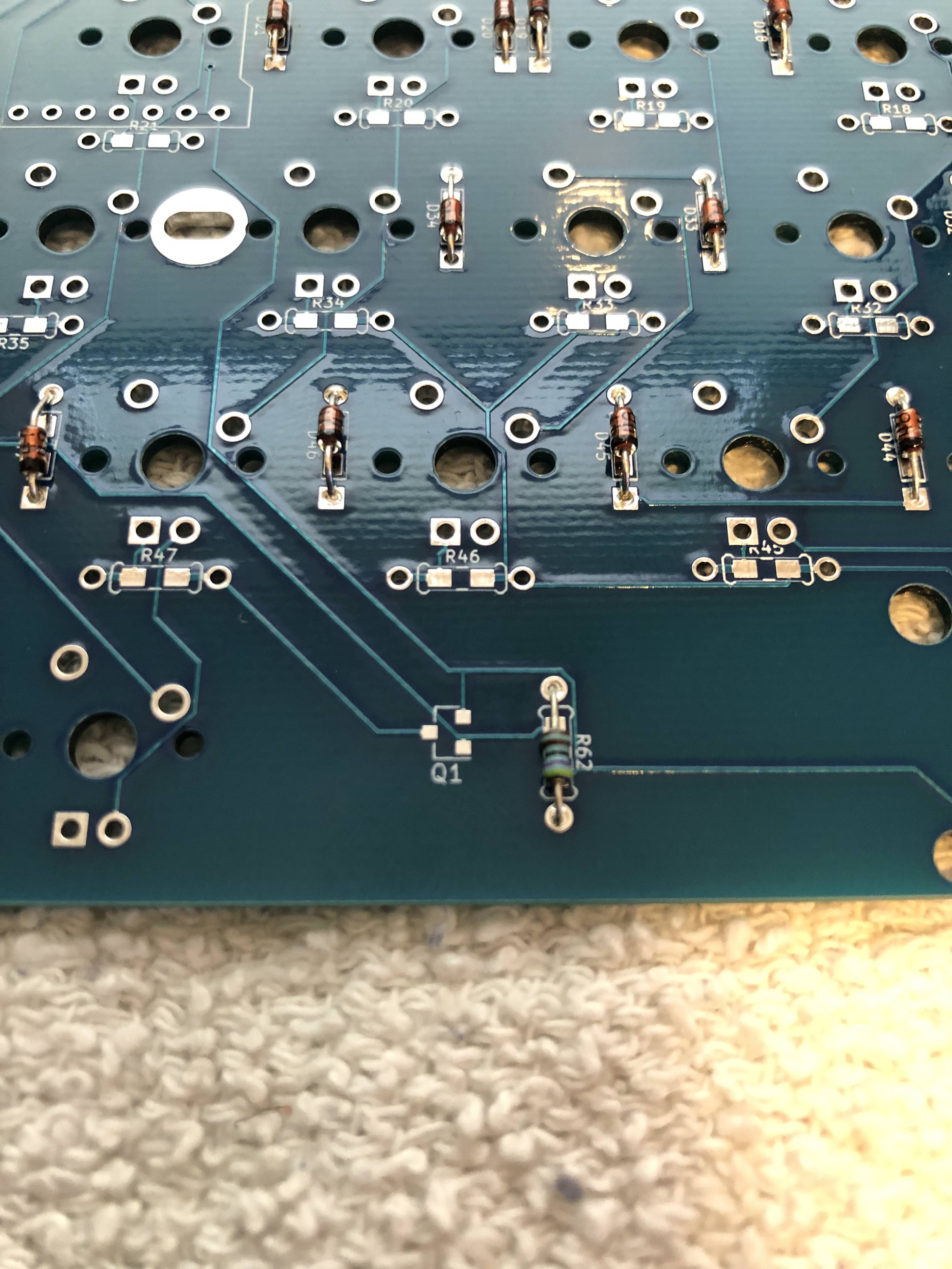
- Next, we're going to solder the 4.7k resistor needed for per-key LED Backlighting. This is optional!
 In this image, it's not labeled, but on newer PCBs, the pad is labeled with a note "4.7k"
 - The 4.7k resistor The color bands are "Yellow, Violet, Red, Gold". Solder it on just like the diodes.
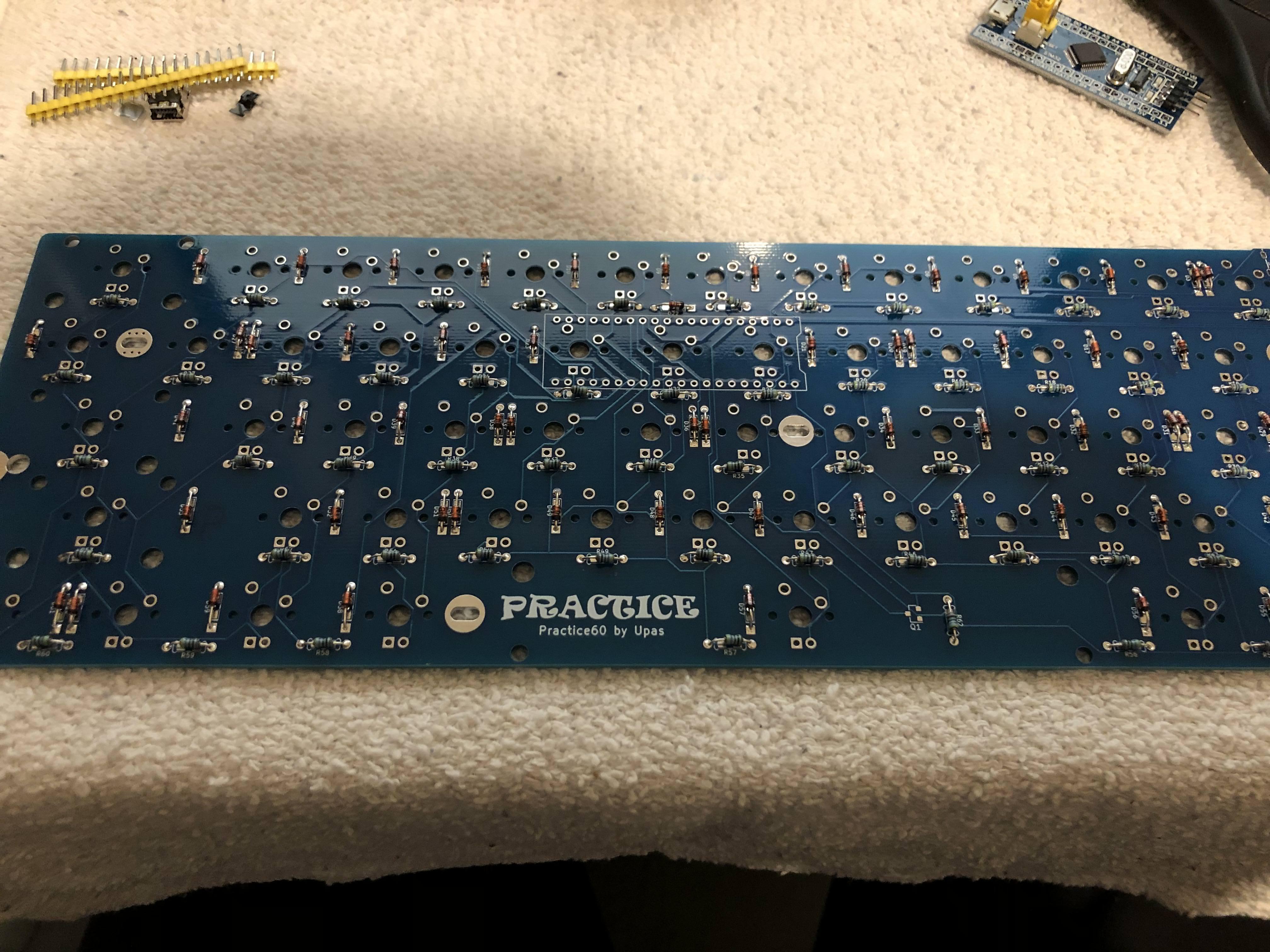
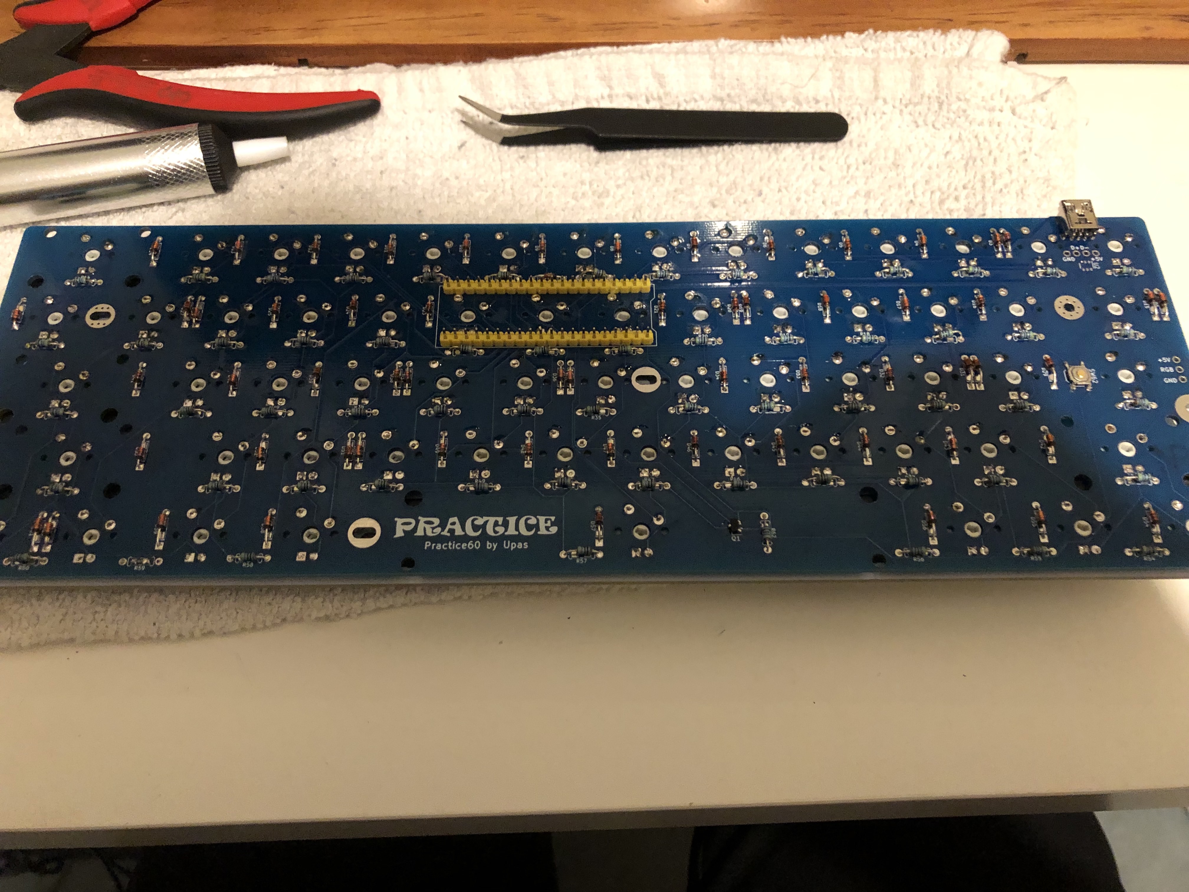
- Solder all the 61 resistors on, using the same technique practiced on the diodes. Orientation doesn't matter. You don't have to save the resistor legs.
-
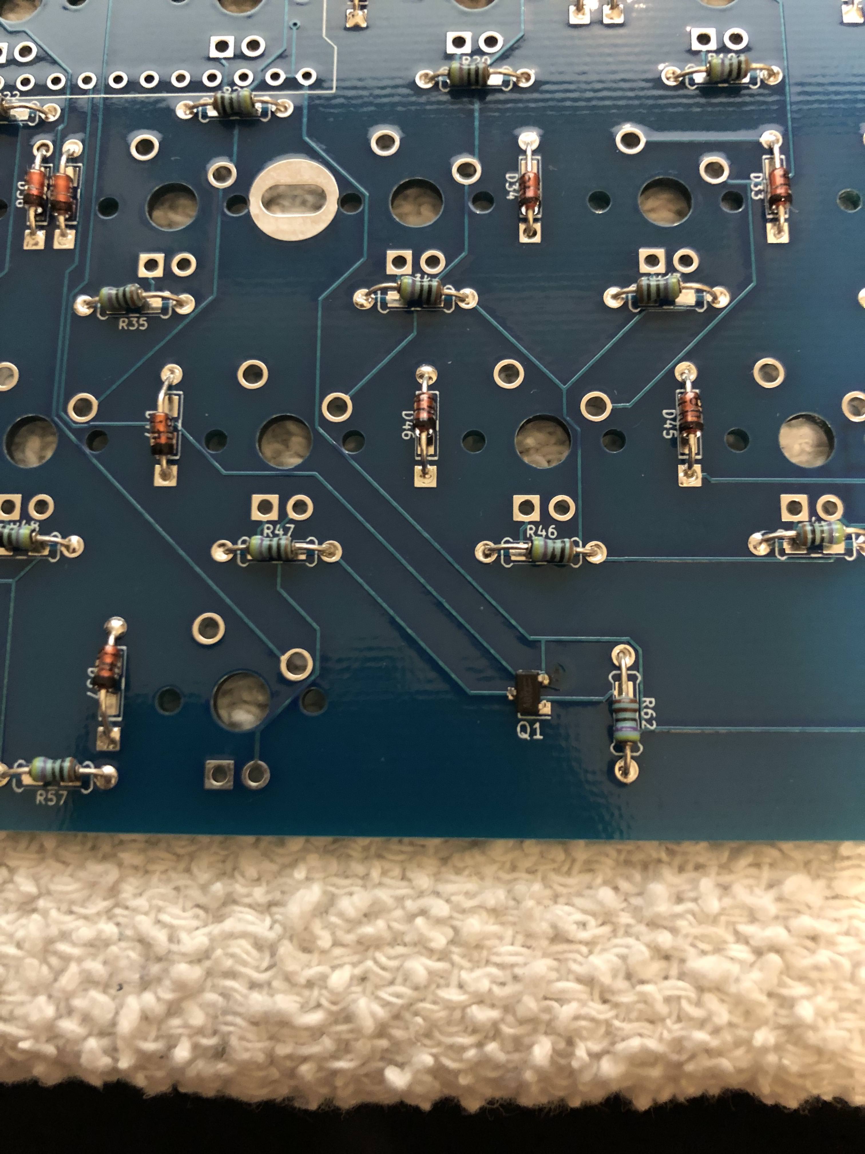
When you're done, your board should look something like this:
Mandatory
After this block, steps are mandatory unless otherwise noted!
ESD Protection Chip (Optional)
Optional
This step is optional. Sometimes there can be electrostatic discharge on your USB lines. This chip will help stop damage from that, but isn't necessary. I only reccommend doing this if you are confident you can do it. If you're newer to soldering, you can jump to the next mandatory section
- The ESD component goes on "U1" on the Ortho48 and Ortho60, and "U2" on the Practice60. We need to identify Pin 1. There is a short line and a long line next to the footprint. Pin 1 is the pin with the long line.
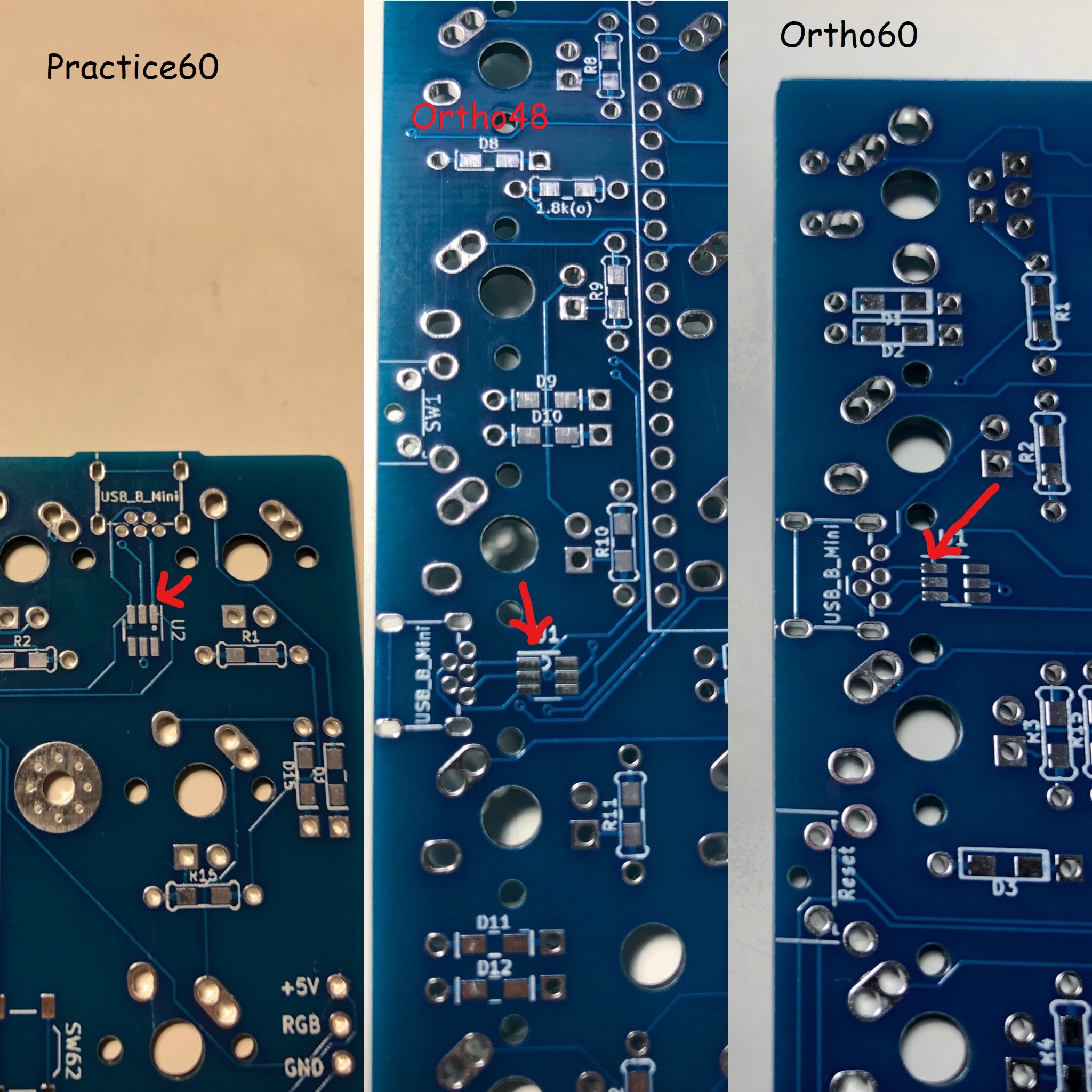
- Identify Pin 1 on the ESD Chip. There is a dot over Pin1. When we solder, we will align the pin 1 on the chip to pin 1 on the board.

- Put some solder on pin 1 of the board.
- Similar to the MOSFET, use your tweezers to hold the component in place, and your iron to melt the solder on Pin 1. Align the ESD chip with the footprint, and remove your iron to tack it in place.
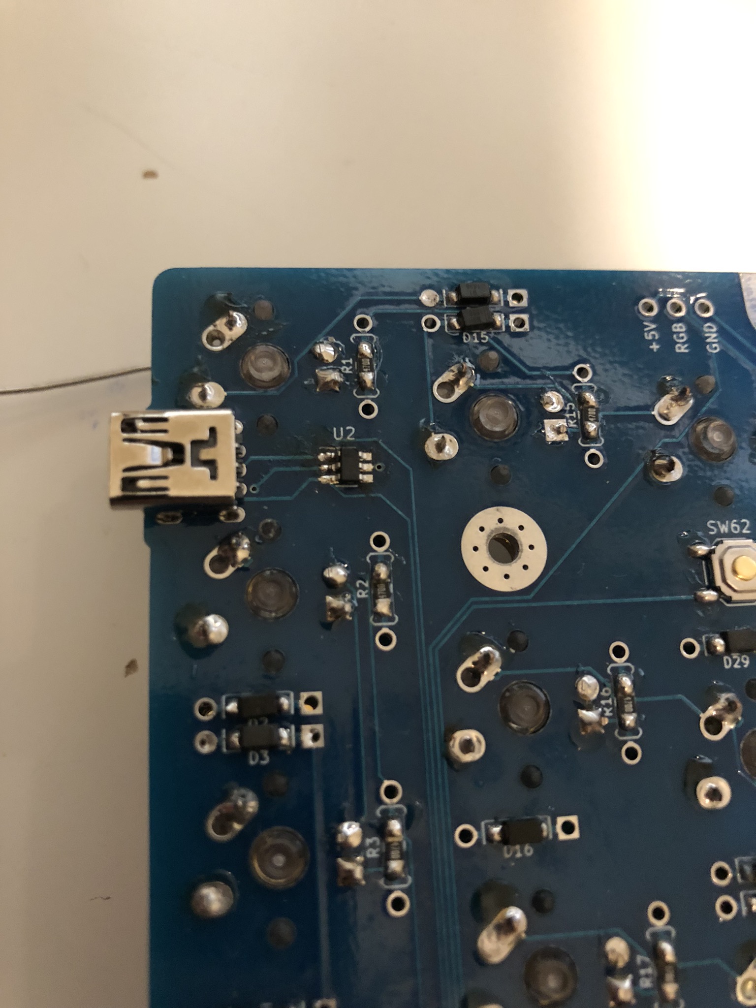
- I like flooding the rest of the pins with flux before soldering the component on. It makes it much easier.
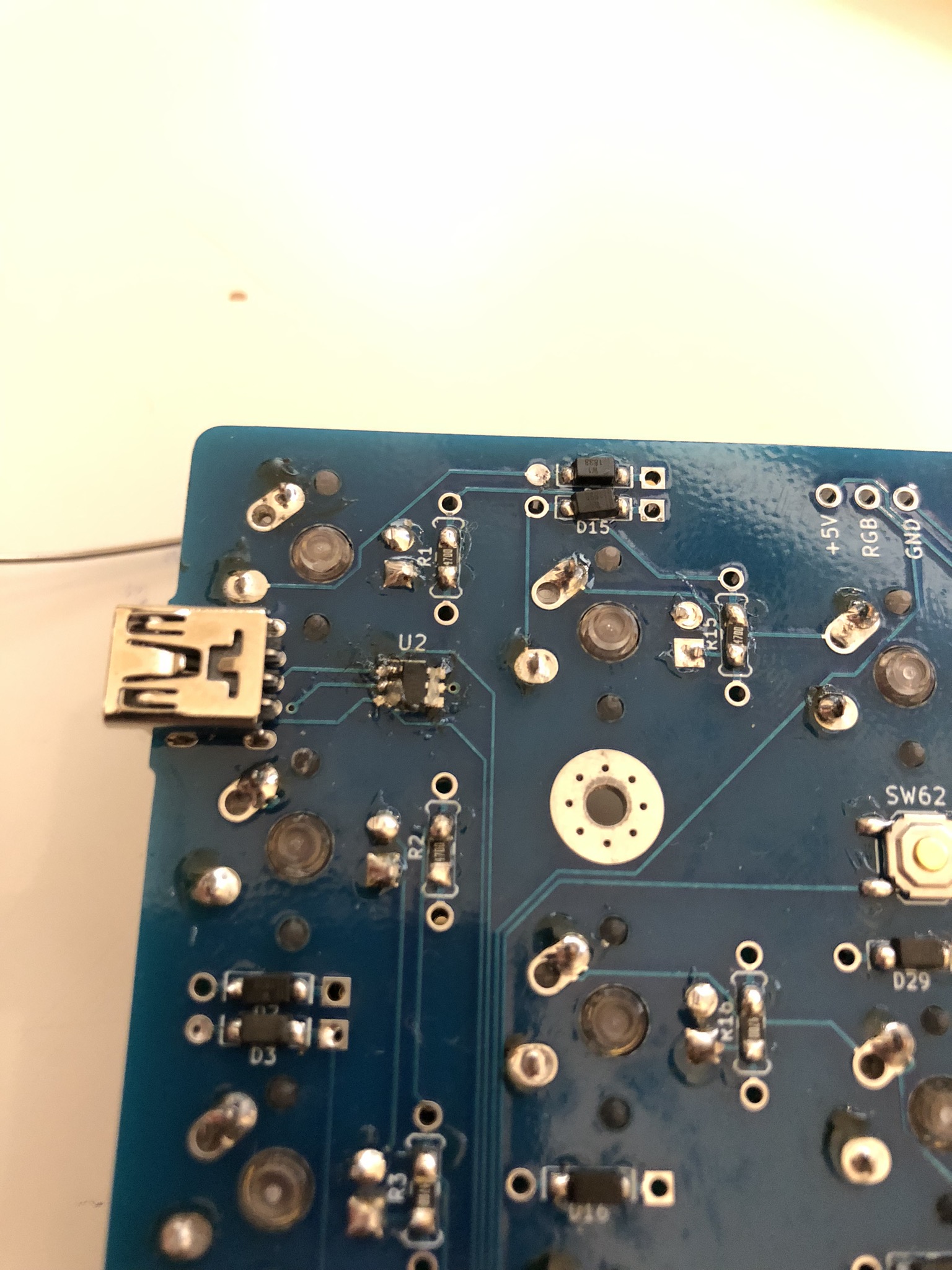
- Solder each remaining pin to the board.
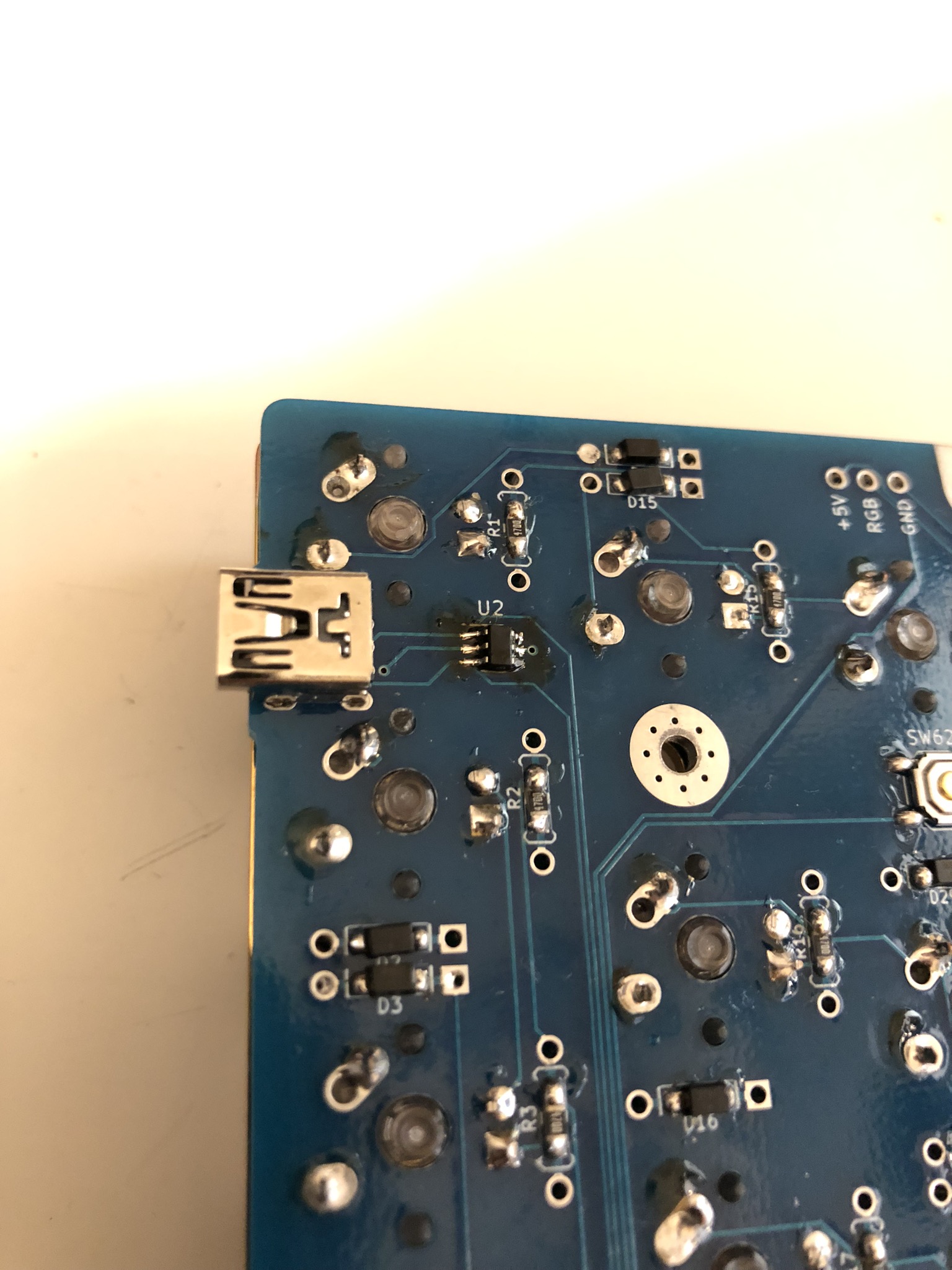
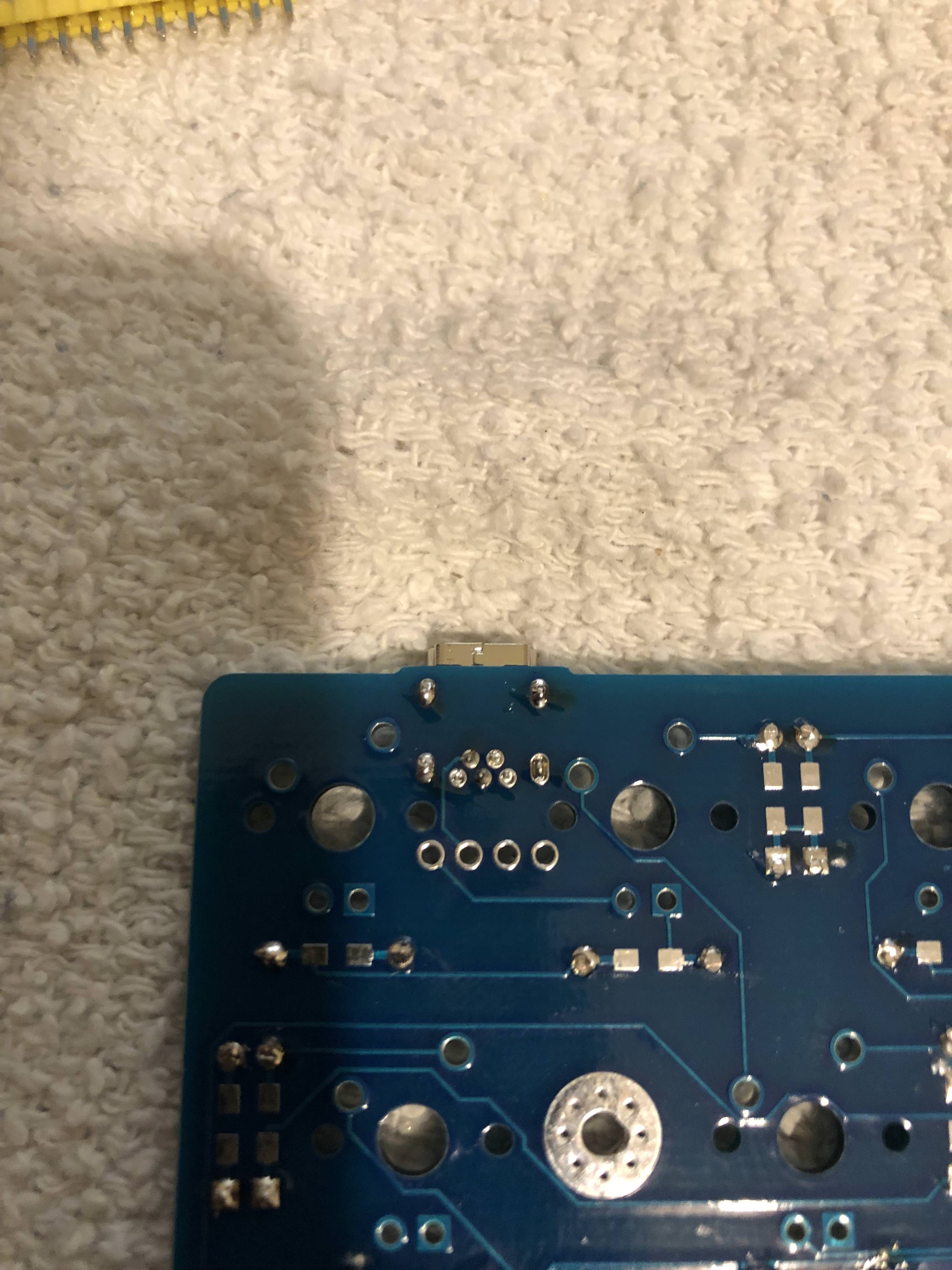
USB Port
- Next we'll solder the USB port. Insert the USB mini port. Make sure all the pins are through the holes.
- Solder the USB mini port
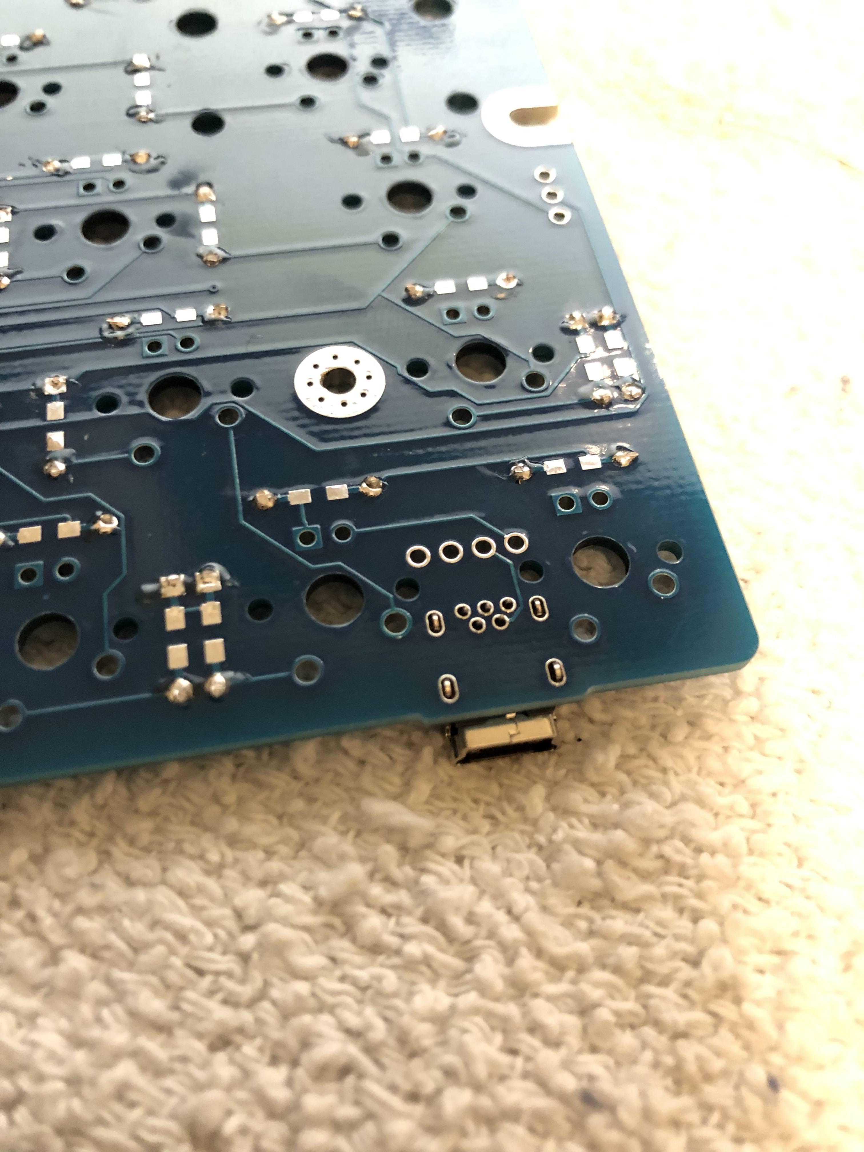
Reset Switch
Note
On both the Ortho48 and Ortho60, you have through hole reset switches, so you won't have to do this SMD soldering! Follow the steps analogous to the USB mini port to install the reset switch.
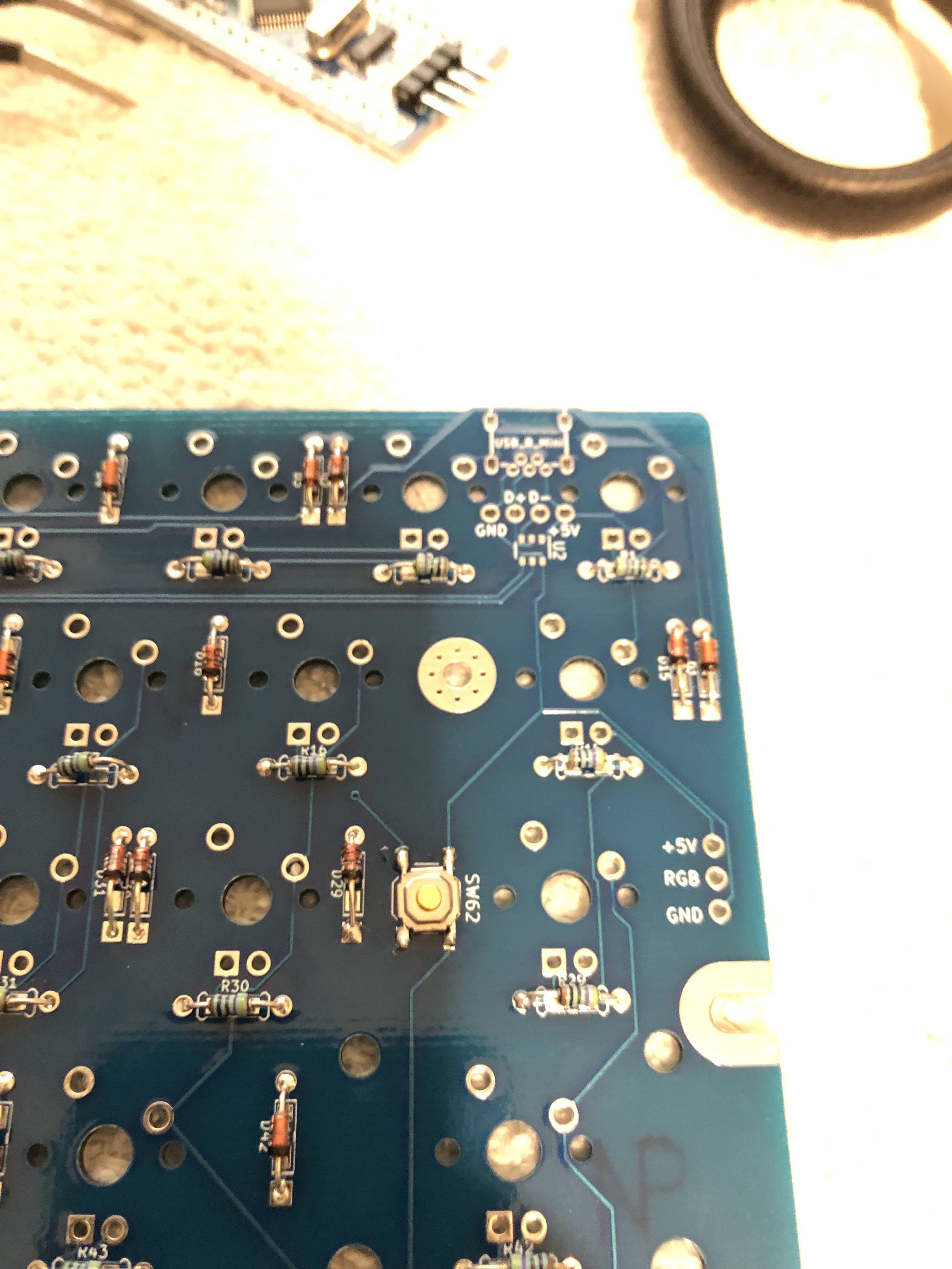
- Practice60: Now we must solder the SMD reset switch. Put a little solder on one of the pads.
- Practice60: Using tweezers, hold the reset switch to the pad, oriented the correct way. Use a soldering iron to make the dot of solder you added heat up, pinning it in place. Solder the reset switch pins to the board.
- On the Ortho60 and Ortho48, insert the angled reset switch into the reset switch spot, and solder like the USB port.
Blue Pill Headers
Warning
If you plan on installing your build in a case, you should use low-profile sockets instead of these headers. There is a low profile socket guide available here. You must use low profile sockets if you want case compatibility! Low profile sockets are also more flexible, and I highly suggest using them!
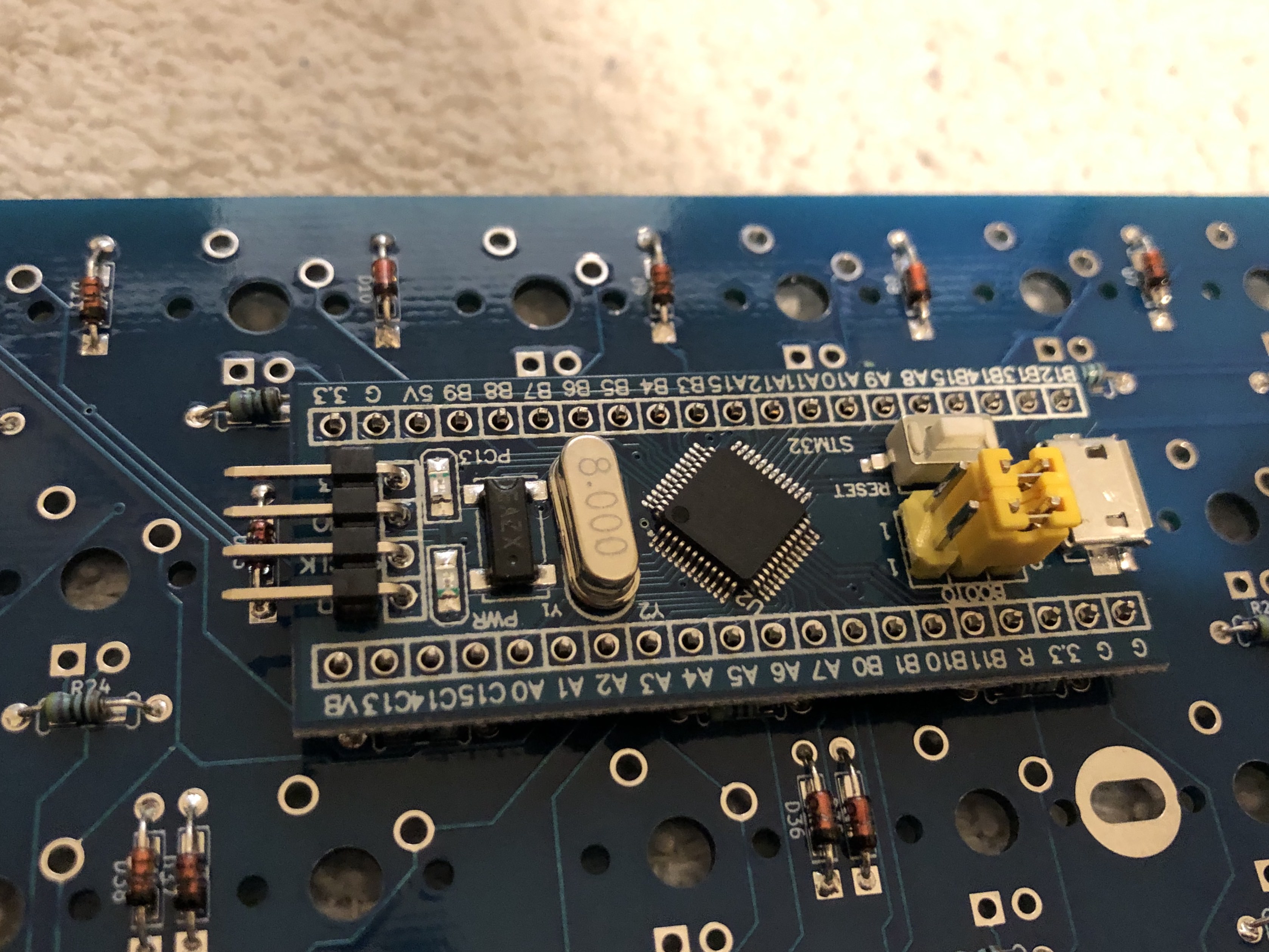
- Next let's put in the headers for our Blue Pill
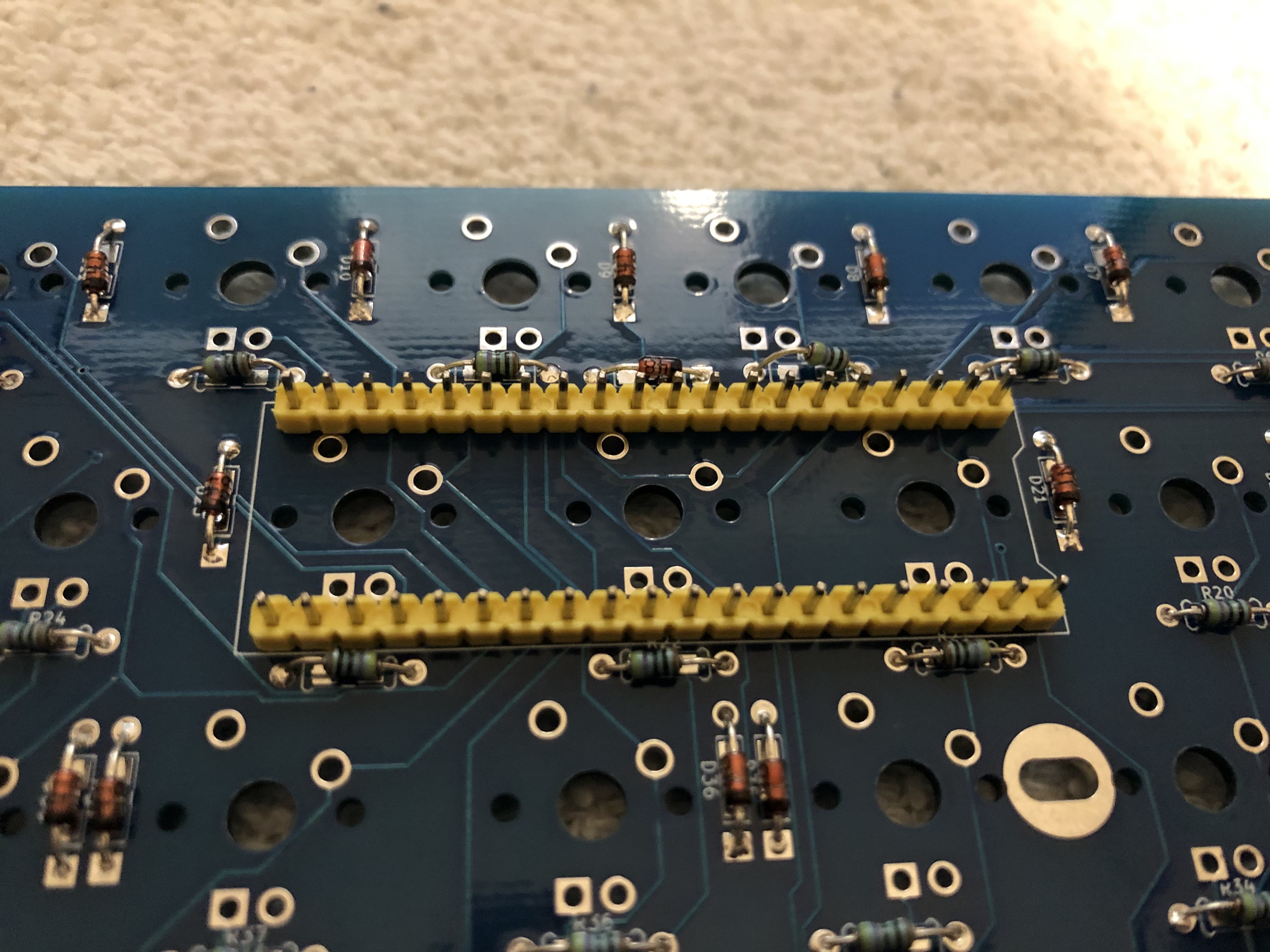
- Use the blue pill to make sure it's aligned! DO NOT SOLDER THE BLUE PILL YET!
- Flip the board to the front, keeping the headers installed.
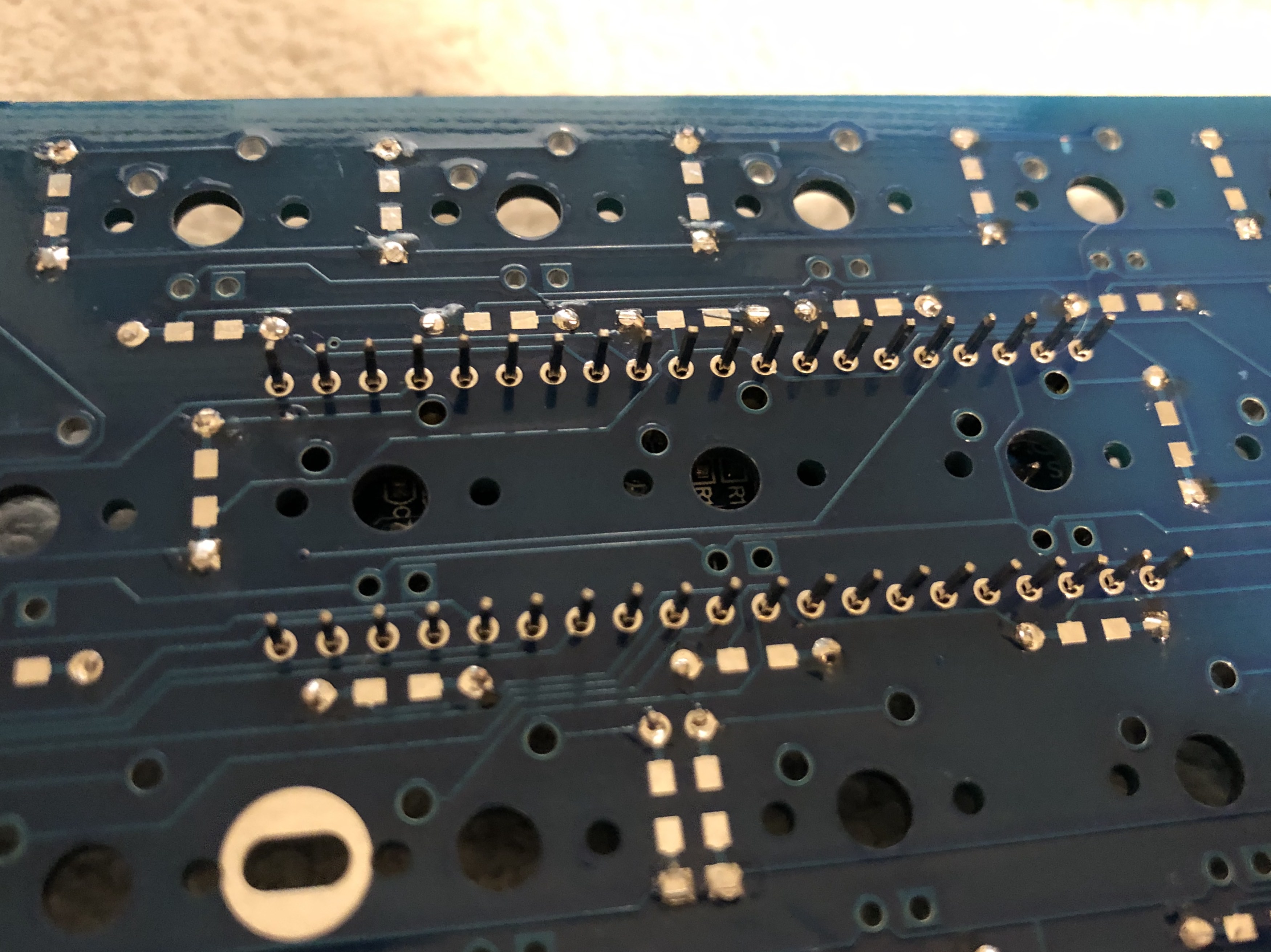
- Solder the headers to the board. You should flush cut them afterwards
Blue Pill Modifications
Note
This section assumes that you've purchased a Blue Pill as part of a kit from me, or from my shop. Most blue pills come with extra jumpers soldered. If this is the case for your Blue Pill, please visit this page for detailed instructions on how to modify it.
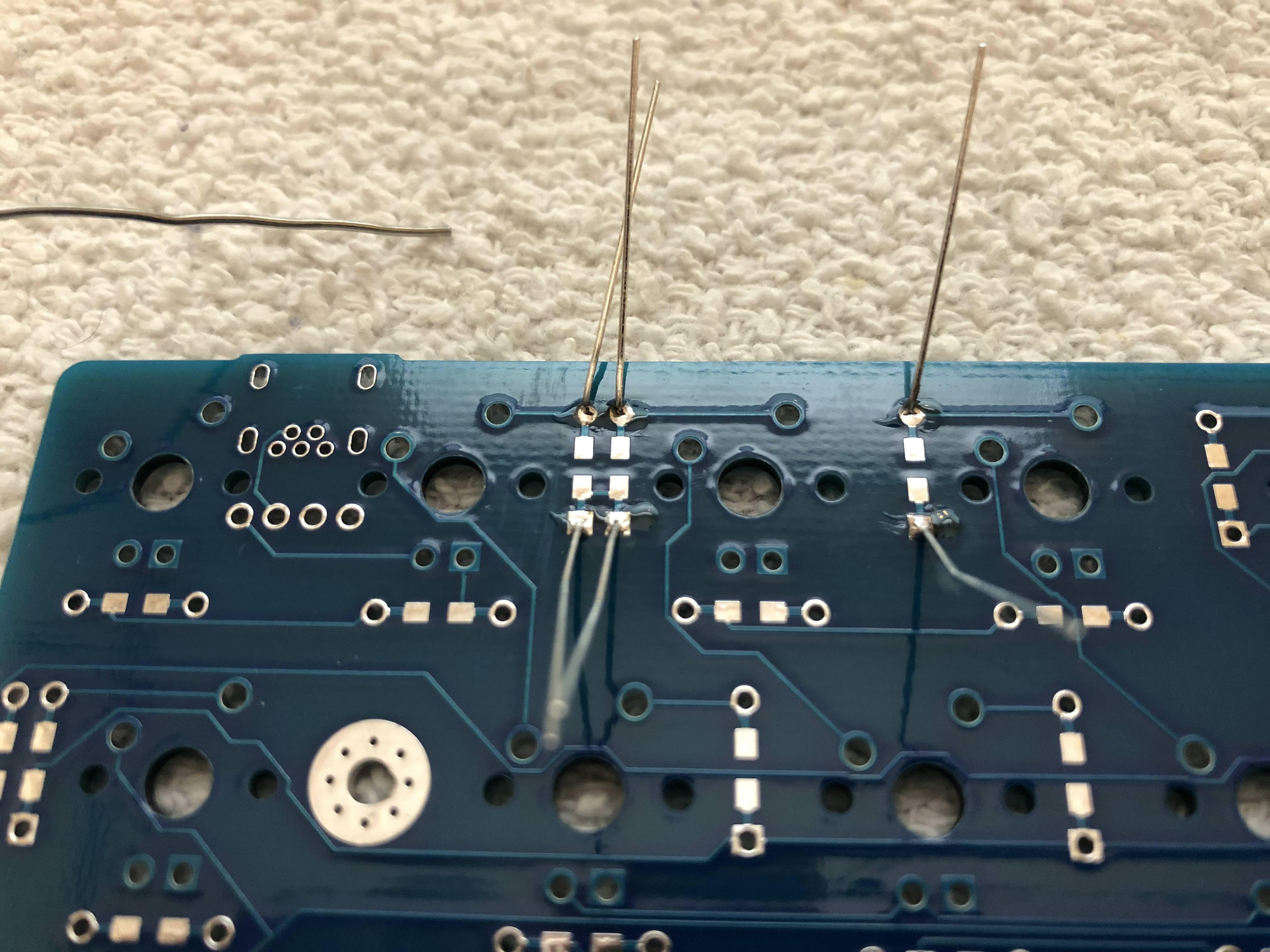
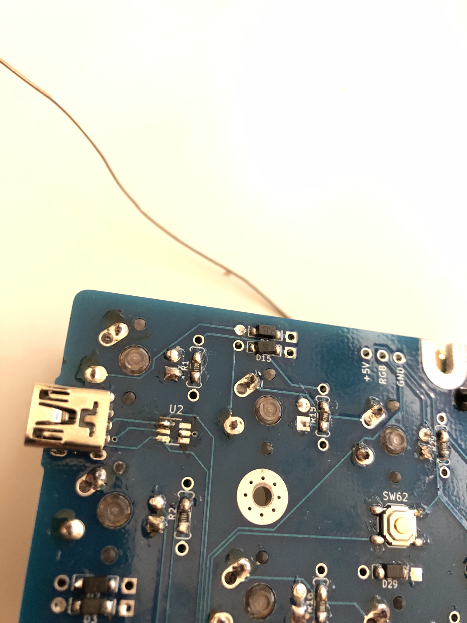
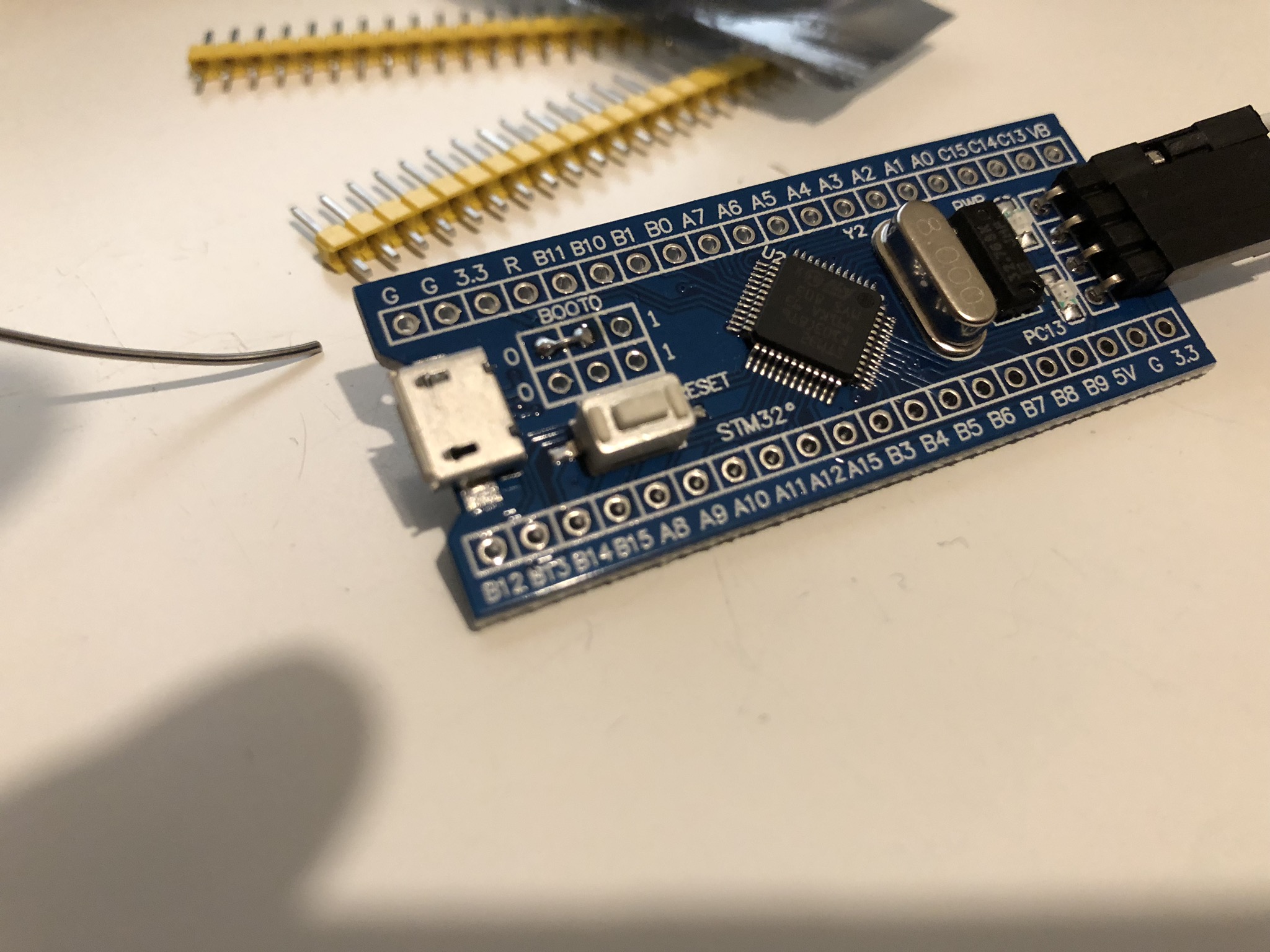
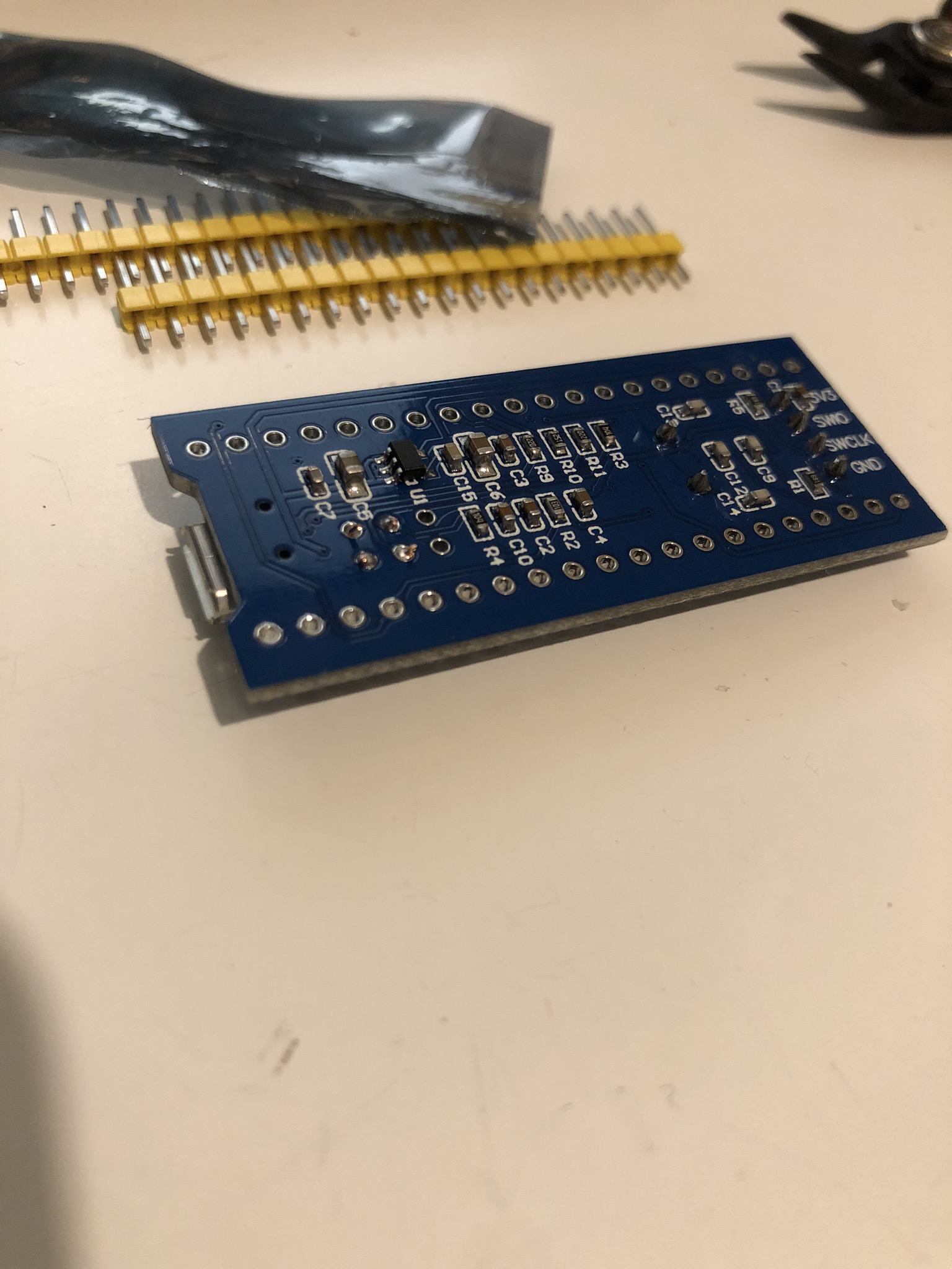
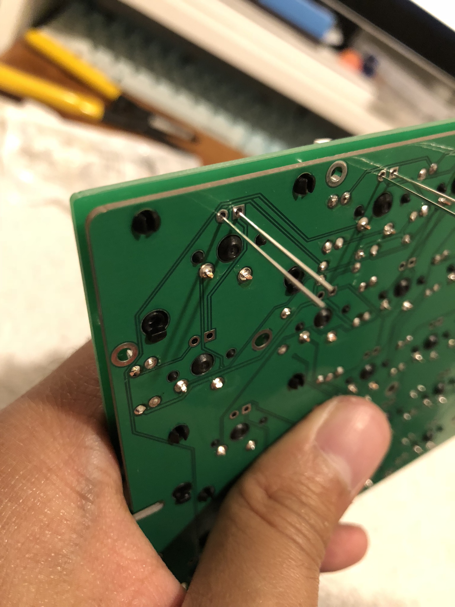
- Since our Bluepills do not have boot jumpers, we need to add some wires to set the boot mode.
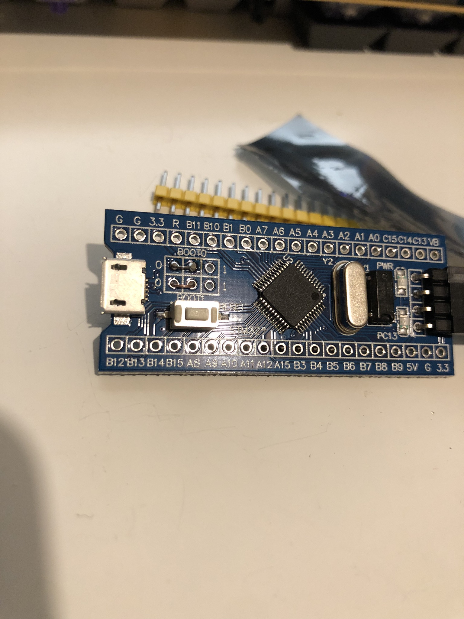
- Put a piece of wire or diode leg between the middle BOOT0 pin and the 0 pin.
- Flip the Bluepill over and solder the wire into the spots.
- Repeat for the BOOT1 pin, again connecting the middle pin to 0.
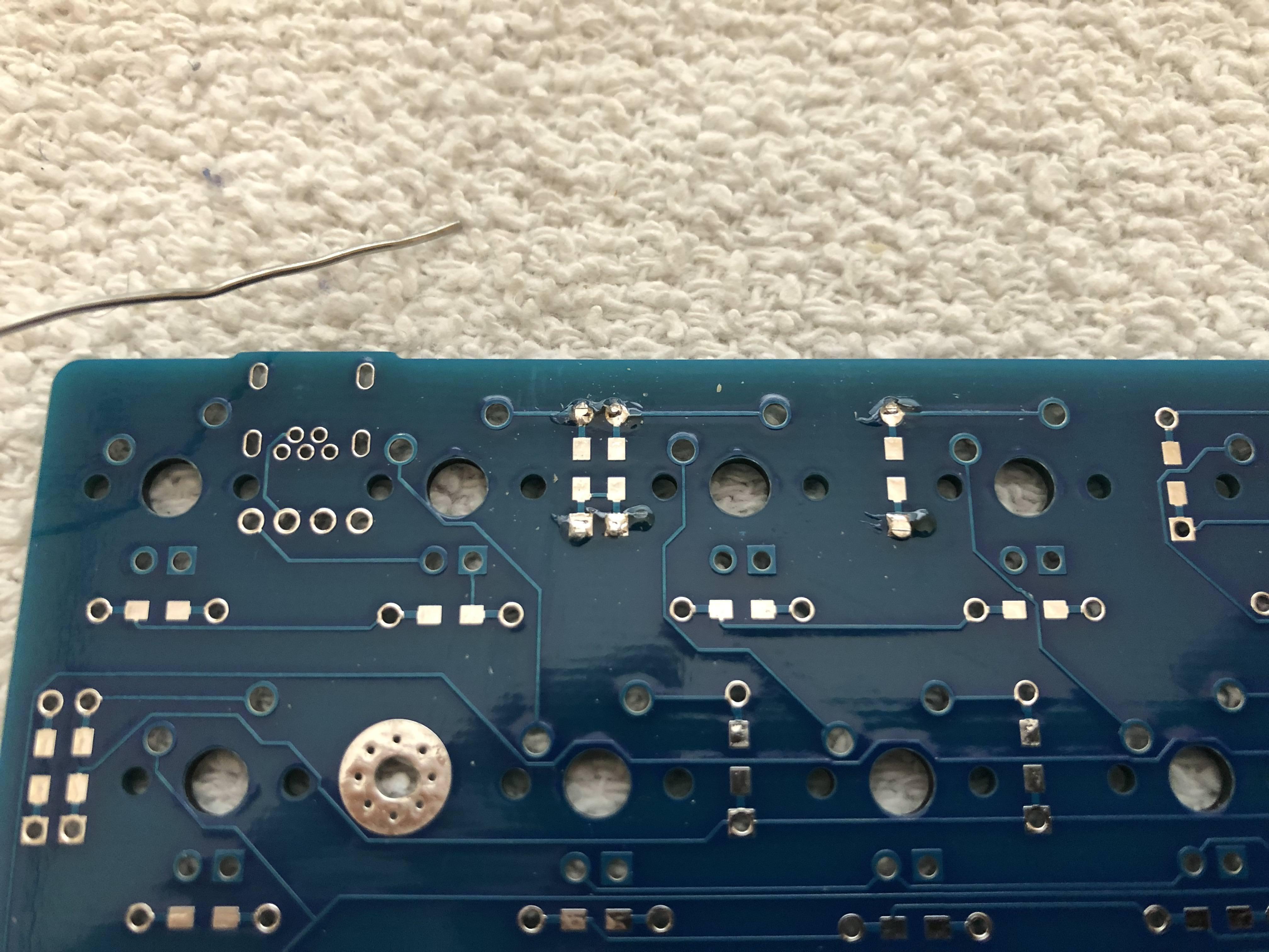
- Cut the extra wire/diode legs off the back of your blue pill.
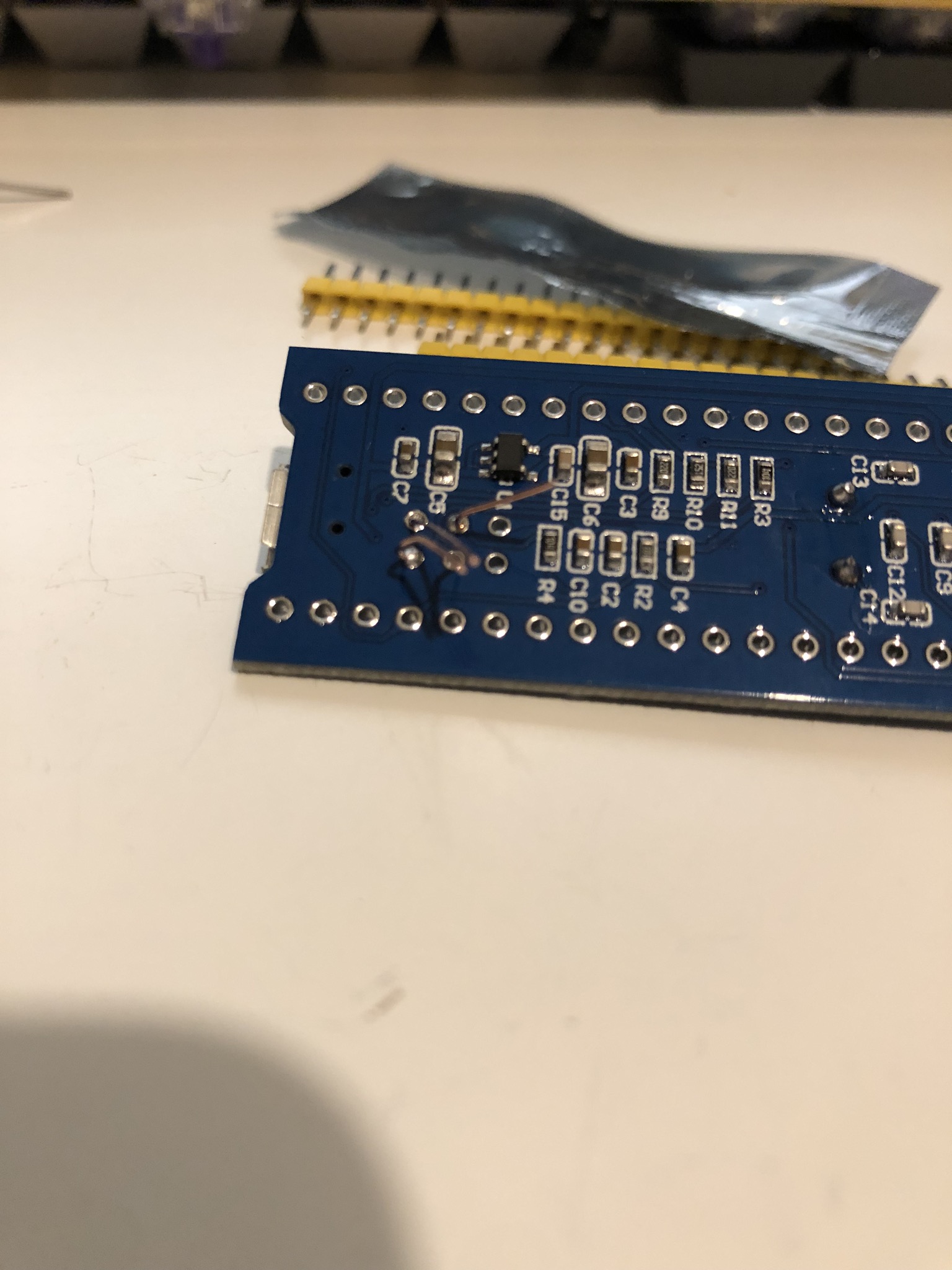
- At the end of this, your Bluepill should look like this:
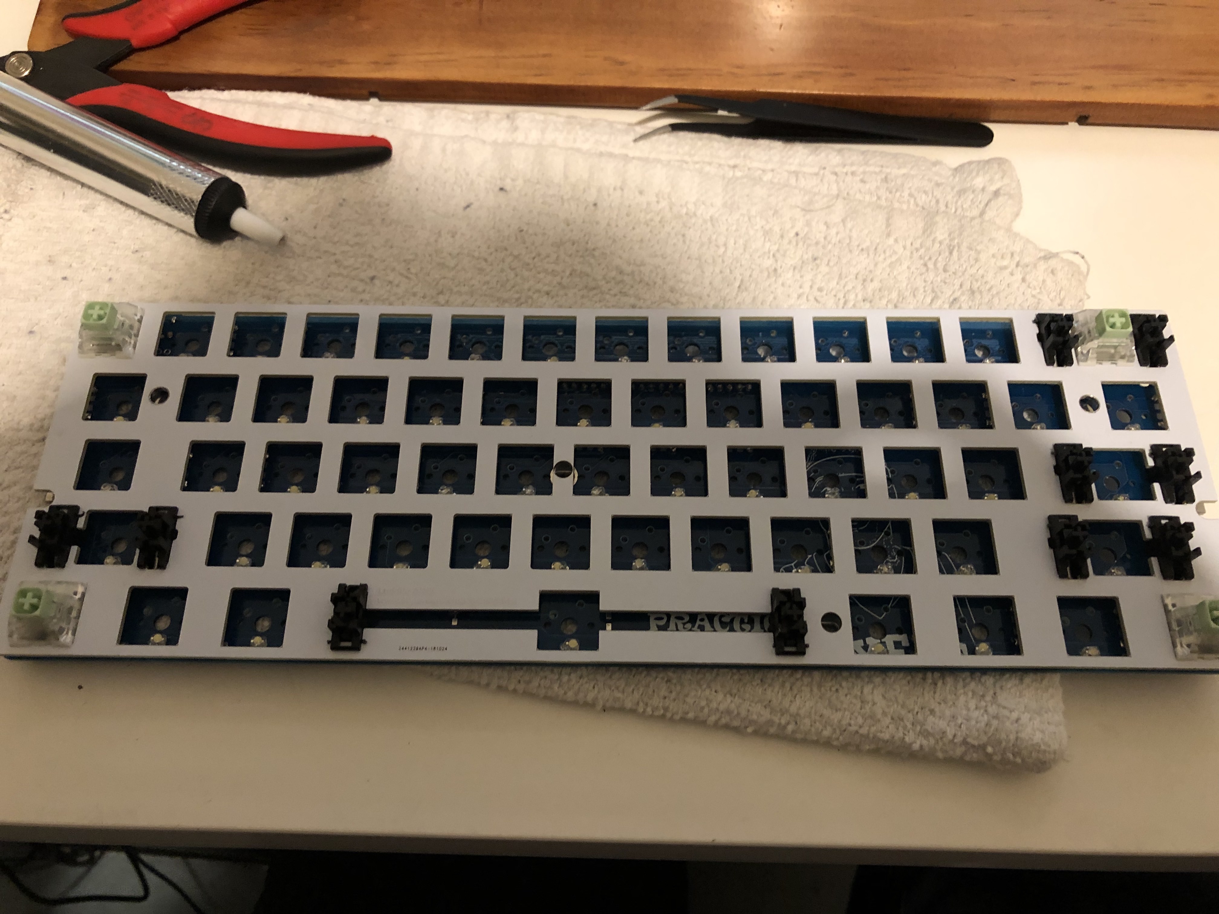
Stabilizers
- Next, we need to install our stabilizers. I recommend clipping and lubing the stabilizers prior to installation.

- Once the stabs are done, let's put switches in the plate, and the plate on the PCB. Make sure the switch legs make it through the holes. I like starting with the 4 corners. Flip the board to the back, and solder the switches.
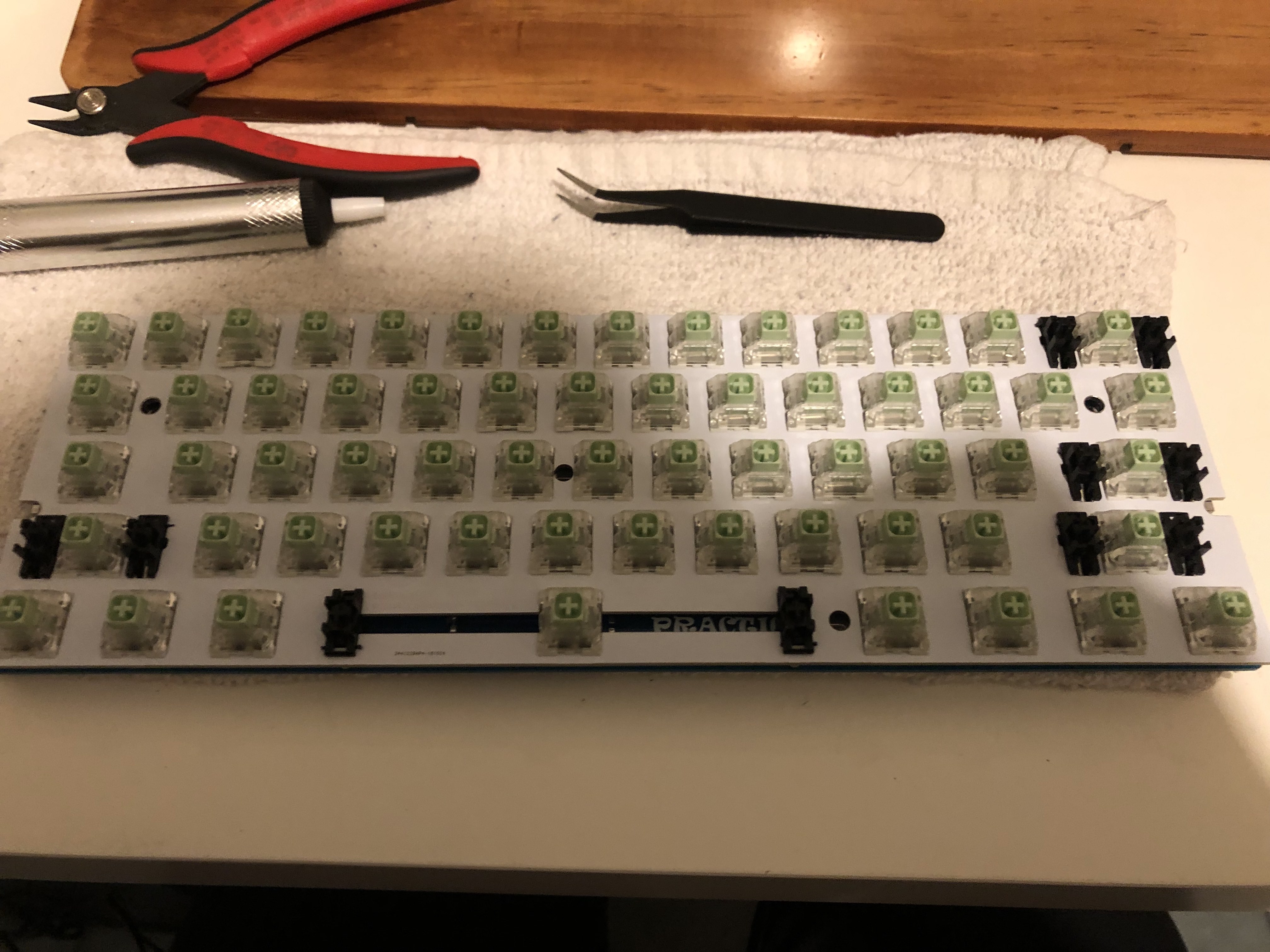
Switches
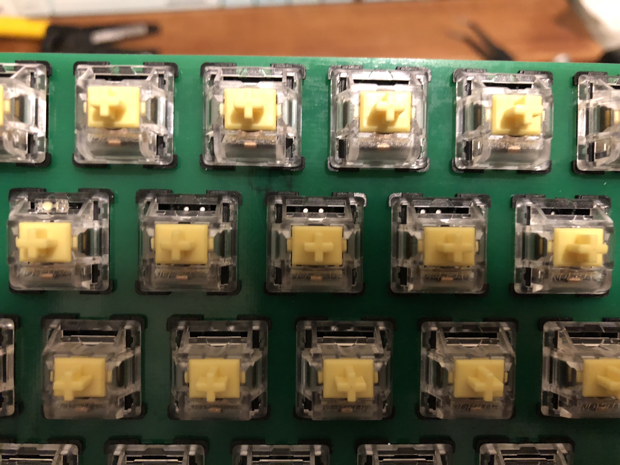
- Finish the rest of the switches following the same strategy.
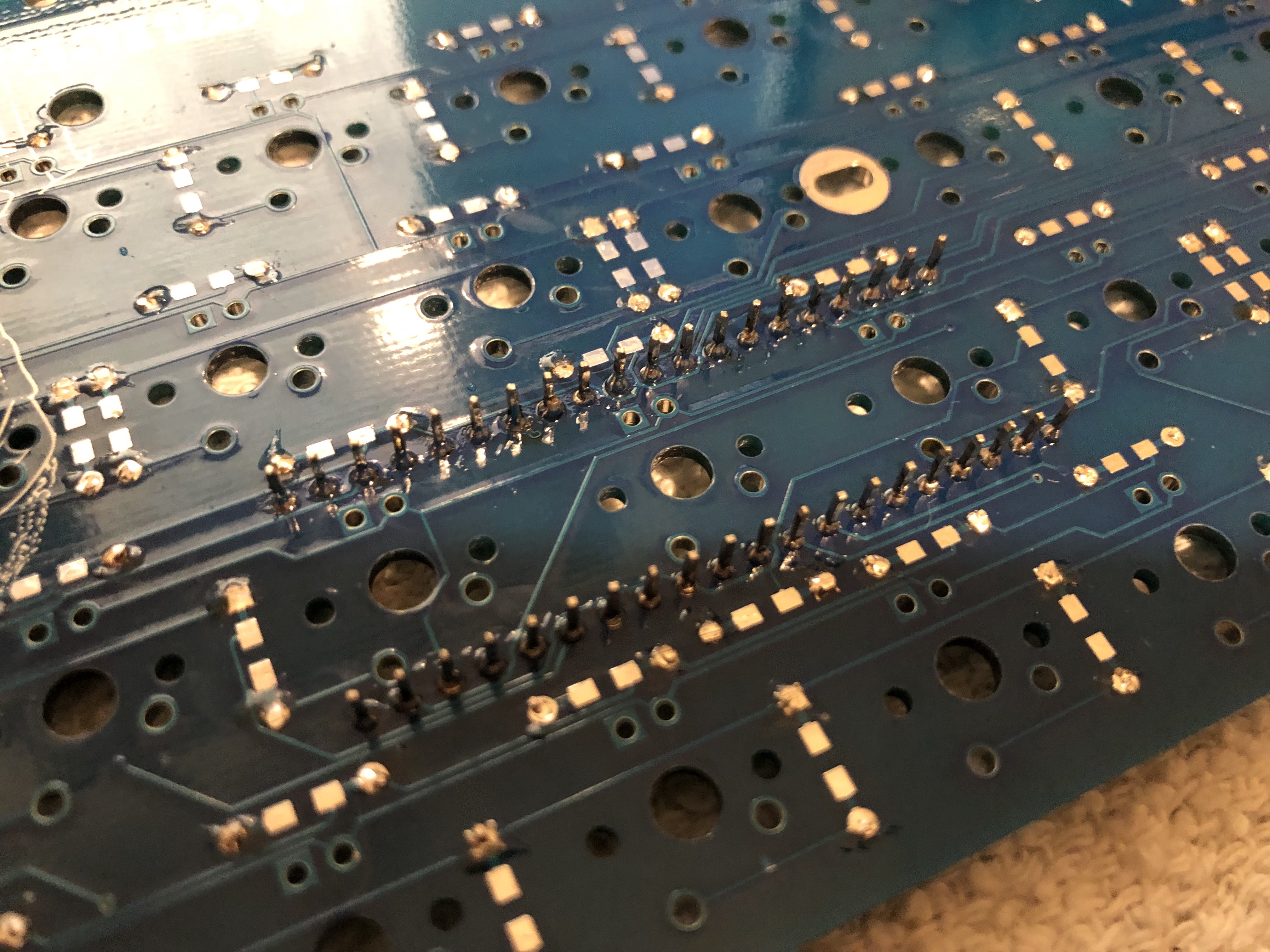
- When the switches are done, the back of the board should look like this.
Installing LEDs
Optional
This step is optional, and only necessary if you want to add per-key LED backlighting to your board. If you want to skip this, you can jump to the next mandatory section
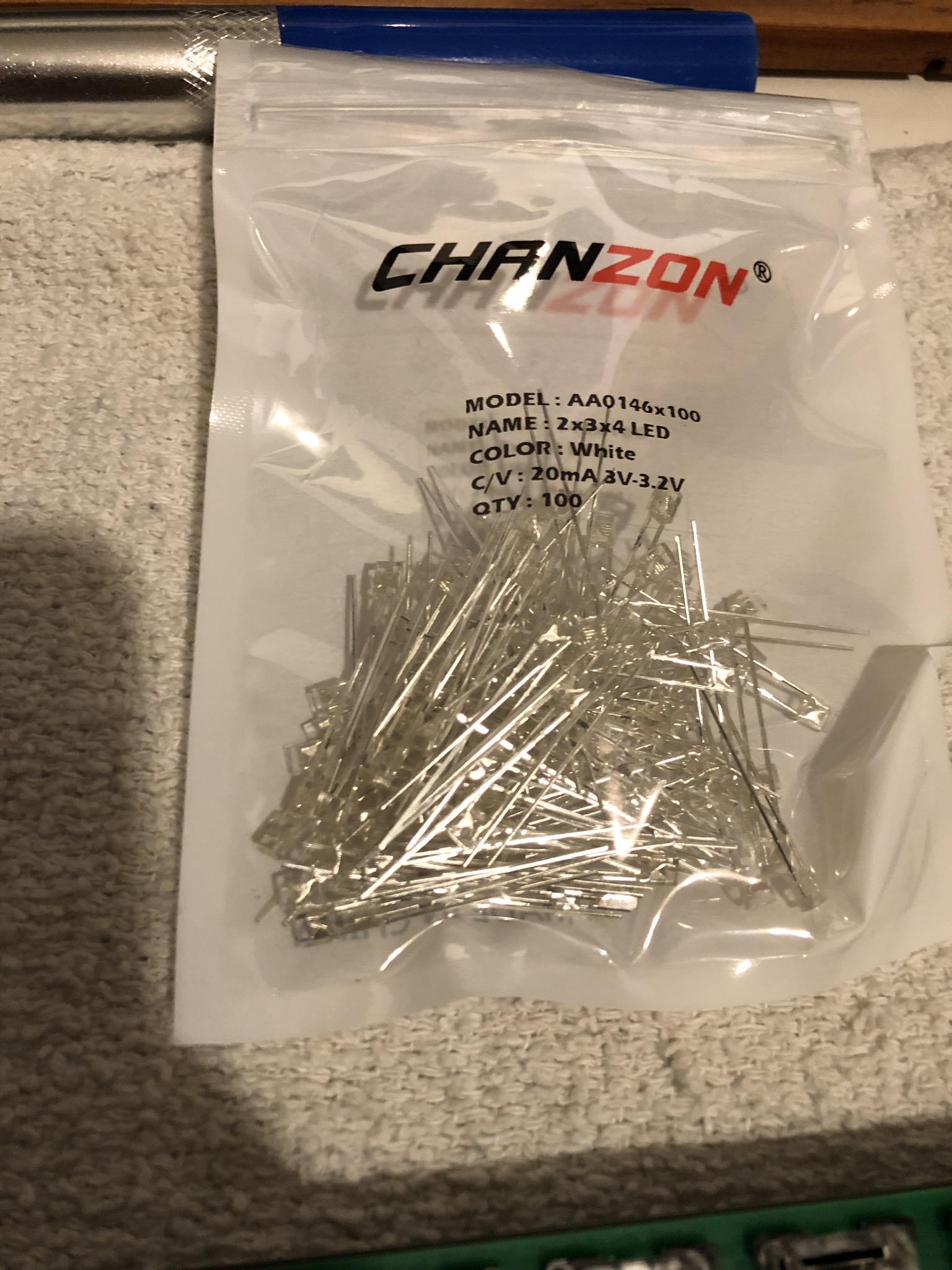
- For backlighting, we support single color LEDS. For this guide, I used white ones:
- On each switch, you should see holes for LEDs:
- We’re going to put the LEDs through these holes. Each LED has a longer side (anode, positive) and a shorter side (cathode, negative). If you notice the PCB, it has square pads and circular pads. The shorter leg of the LED should go into the hole with the square pad.
- Once inserted, bend the legs and follow the same general technique that you did with the diodes and resistors.
Final Installation
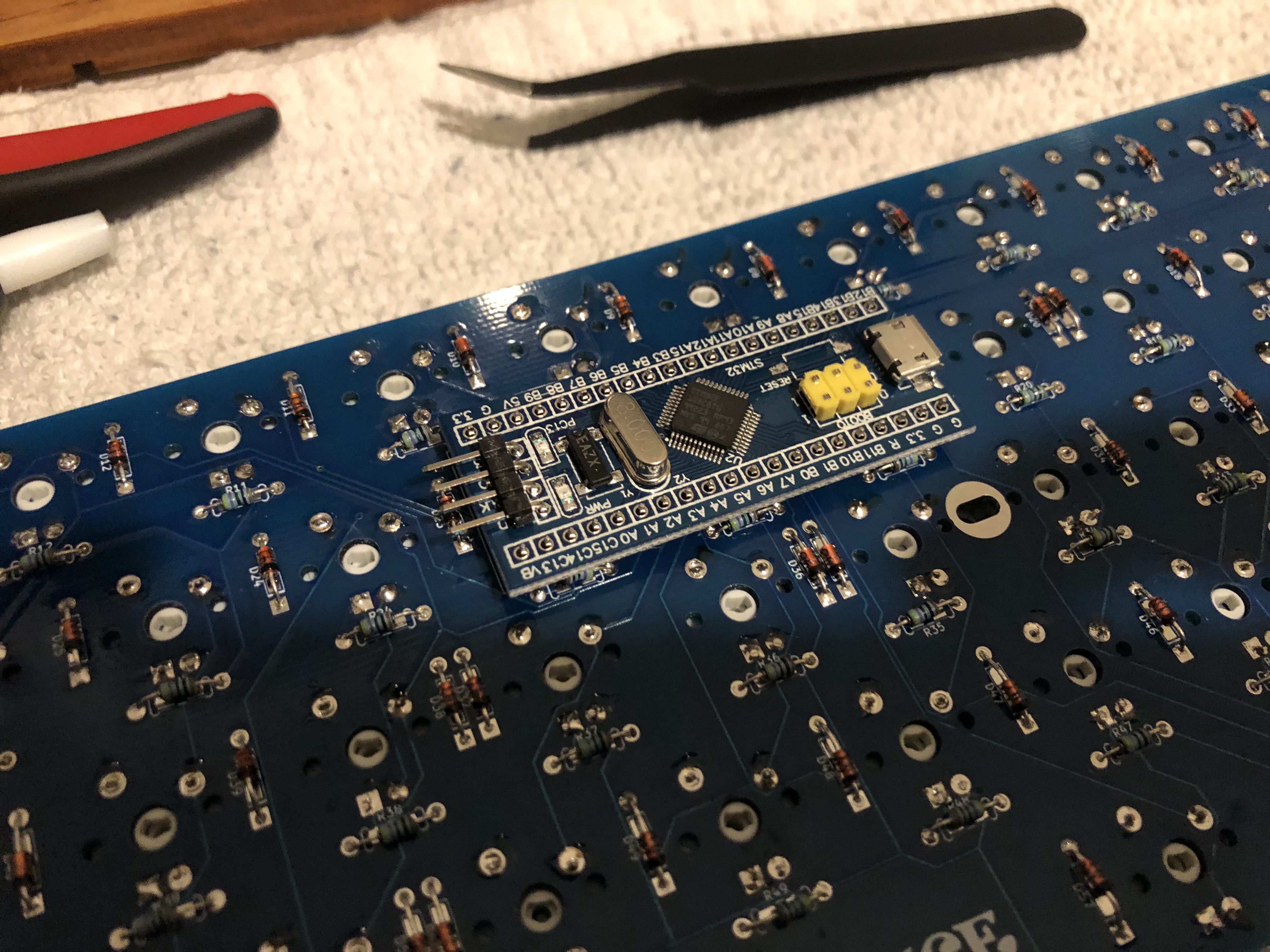
-
Finally, add the blue pill and solder it to the board. Make sure you have it oriented the correct way! Follow the printout on the board. The notch on the outline is where the USB port goes.
Note
TODO: Assemble Sandwich Case. This should be pretty simple, if you need help please contact me on the CannonKeys Discord or through the support email, support
cannonkeys.com