Chimera65 Build Guide
Congrats on your Chimera65 purchase! This is a guide to building your Chimera65.
Parts
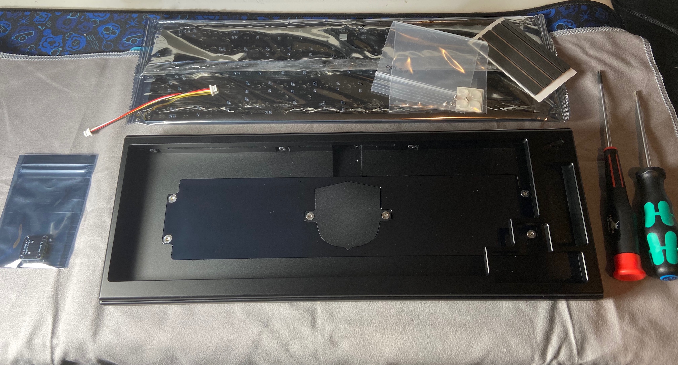
- Chimera65 Case
- Chimera65 PCB
- Daughterboard
- JST Cable
- 12 Poron Strips
- 4 Bumpons
- 4 Small Screws for Daughterboard
Test the PCB
Note
If you are building a round 2 unit, your PCB and Daughterboard will be using a molex connector. This is functionally the same, but will look slightly different than the images in this guide. The molex connectors snap in from the top. We have a video of installing this cable on our C4 Daughterboard listing if you need assistance with this step.
-
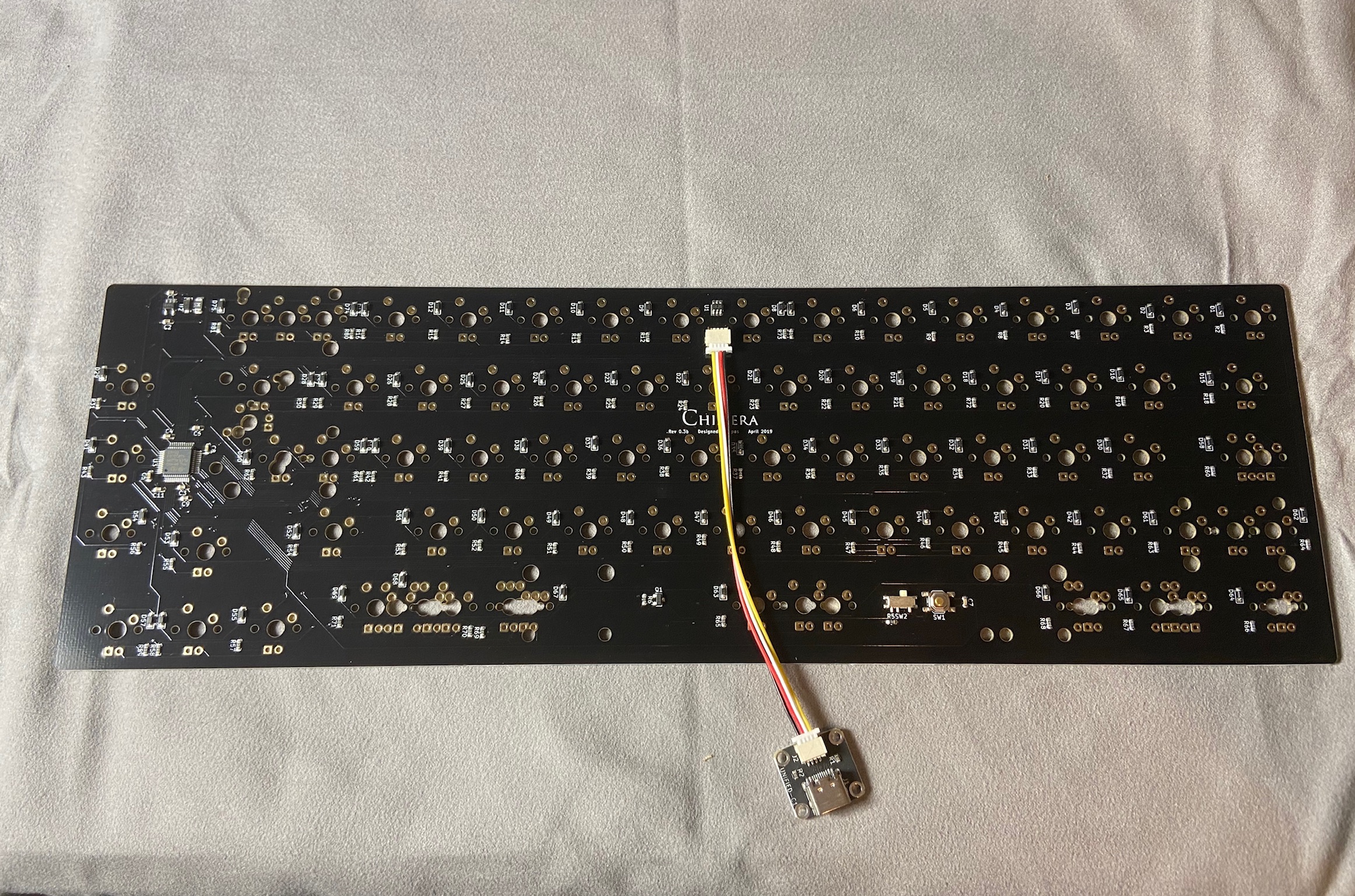
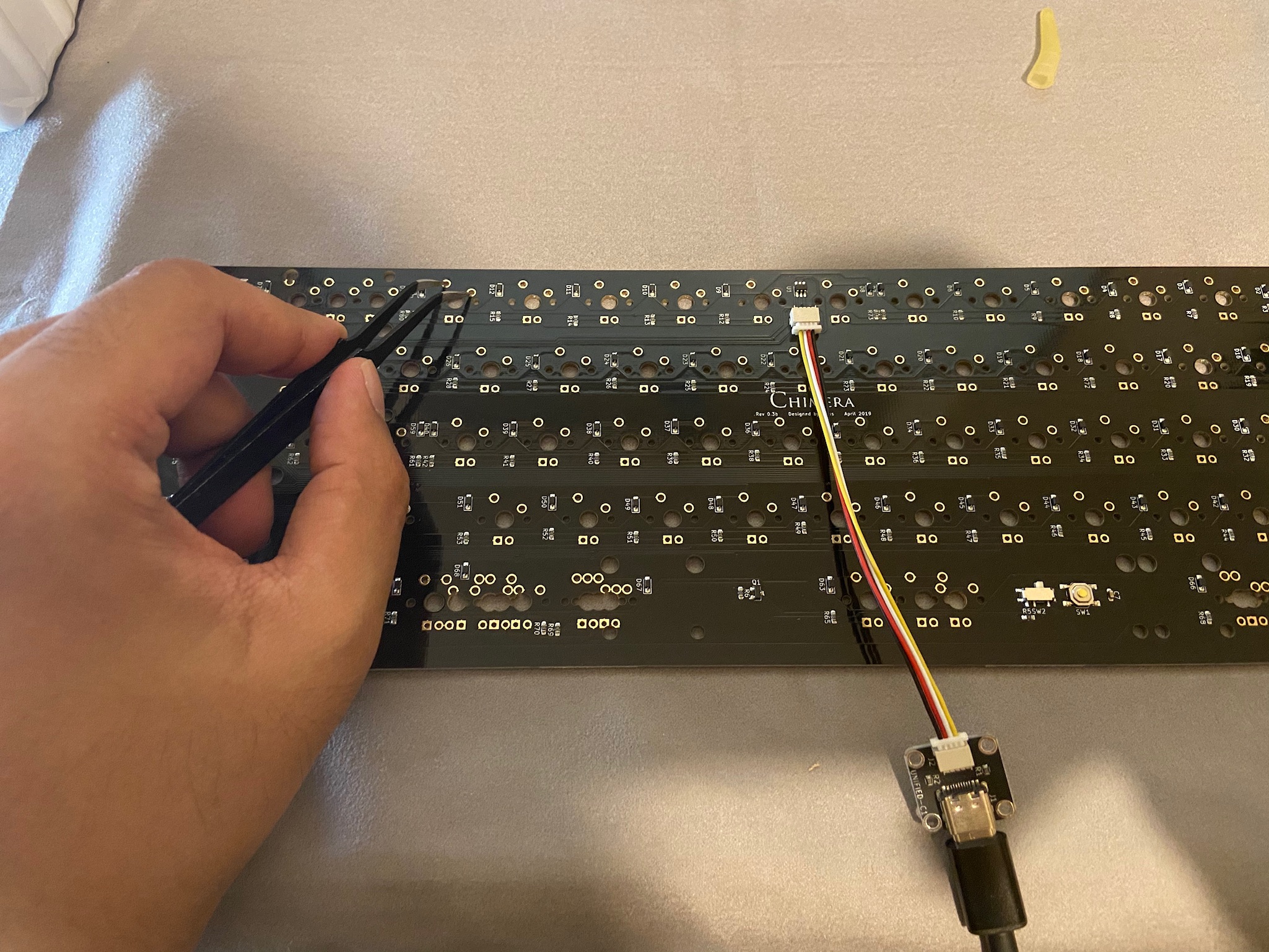
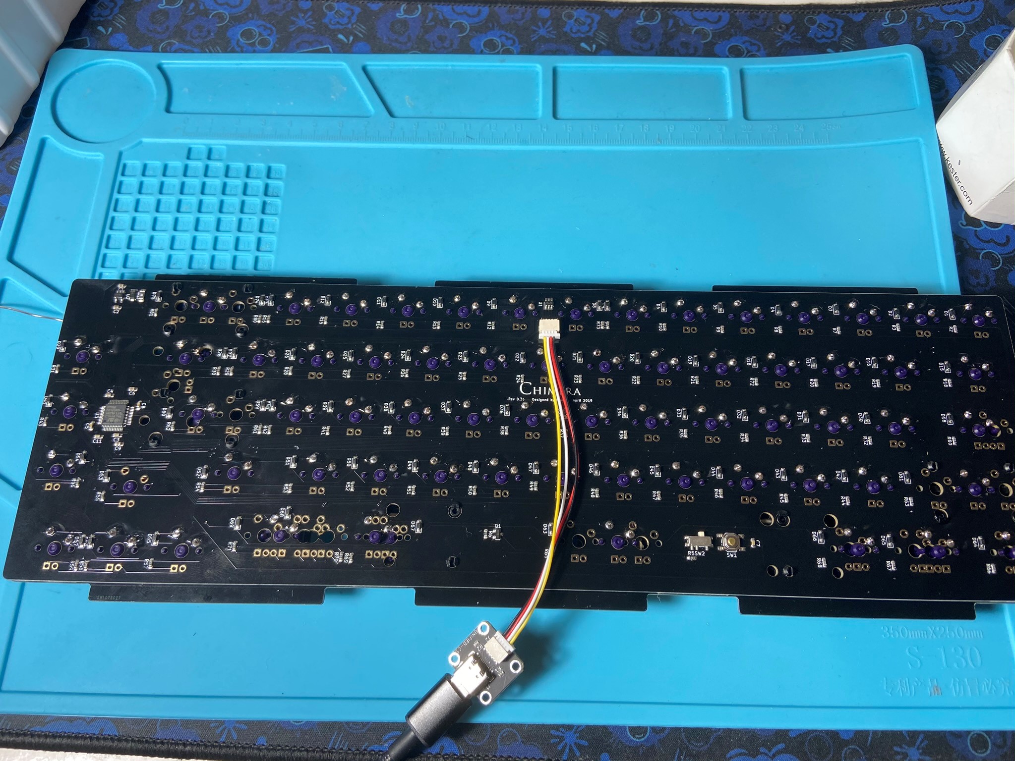
The first thing we have to do is to test the PCB. Use the daughterboard and JST cable and connect them together with the PCB. Be sure to put the JST cable in the right way.
-
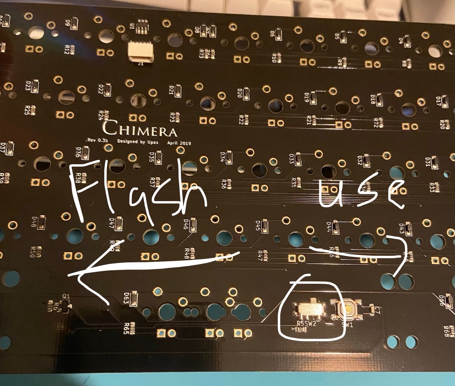
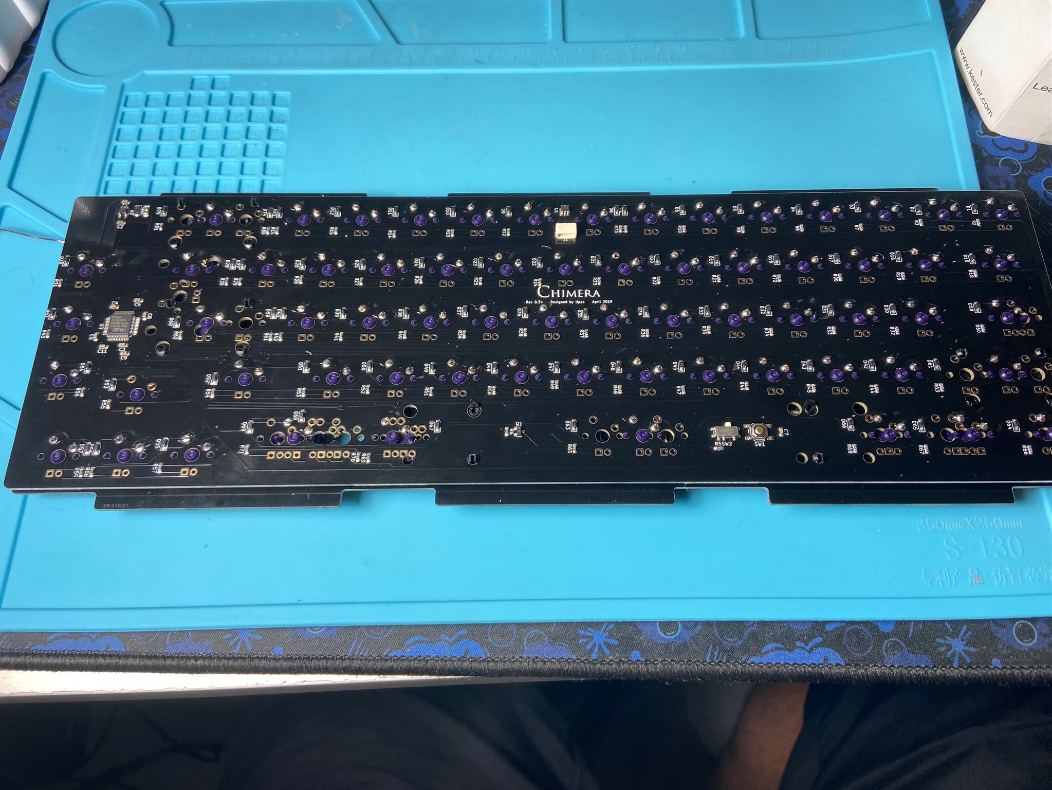
Ensure that the switch on the back of the PCB is set to "keyboard" mode. The other side puts the PCB into flashing mode:
-
Plug in the daughterboard and use tweezers to test each switch footprint for a keypress:
PCB/Plate Assembly
Note
We highly recommend clipping and lubing your stabilizers prior to this step, for optimal feel!
-
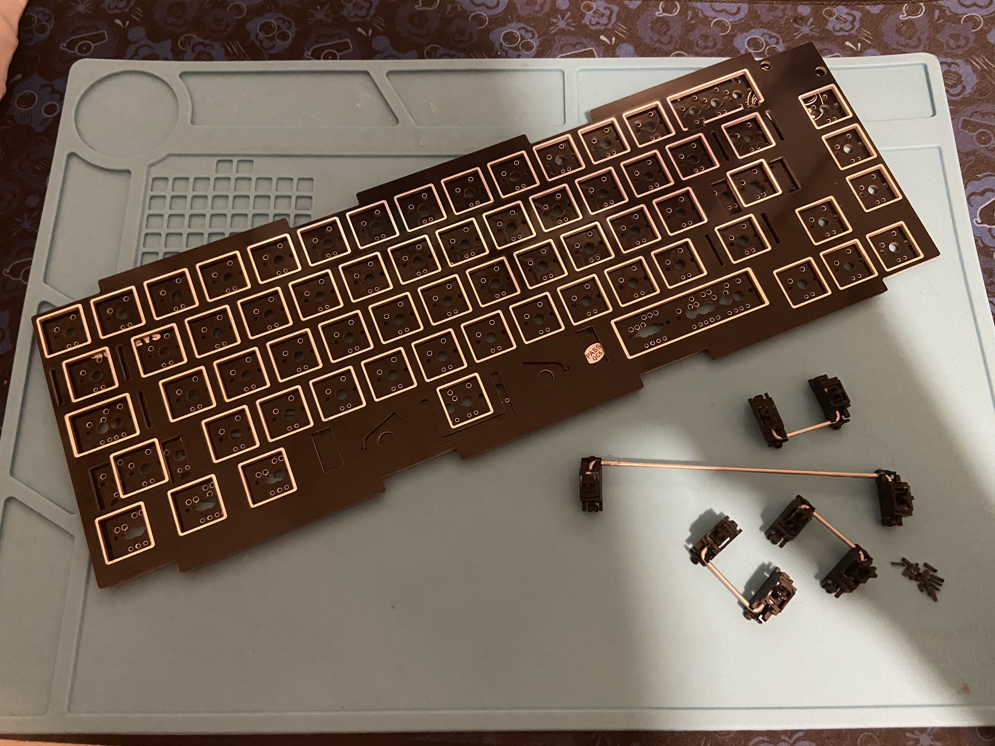
Install your stabilizers in the PCB:
-
Slide your plate over the stabilizers
-
I like to solder and test my stabilized keys before moving on with the rest of the build.
-
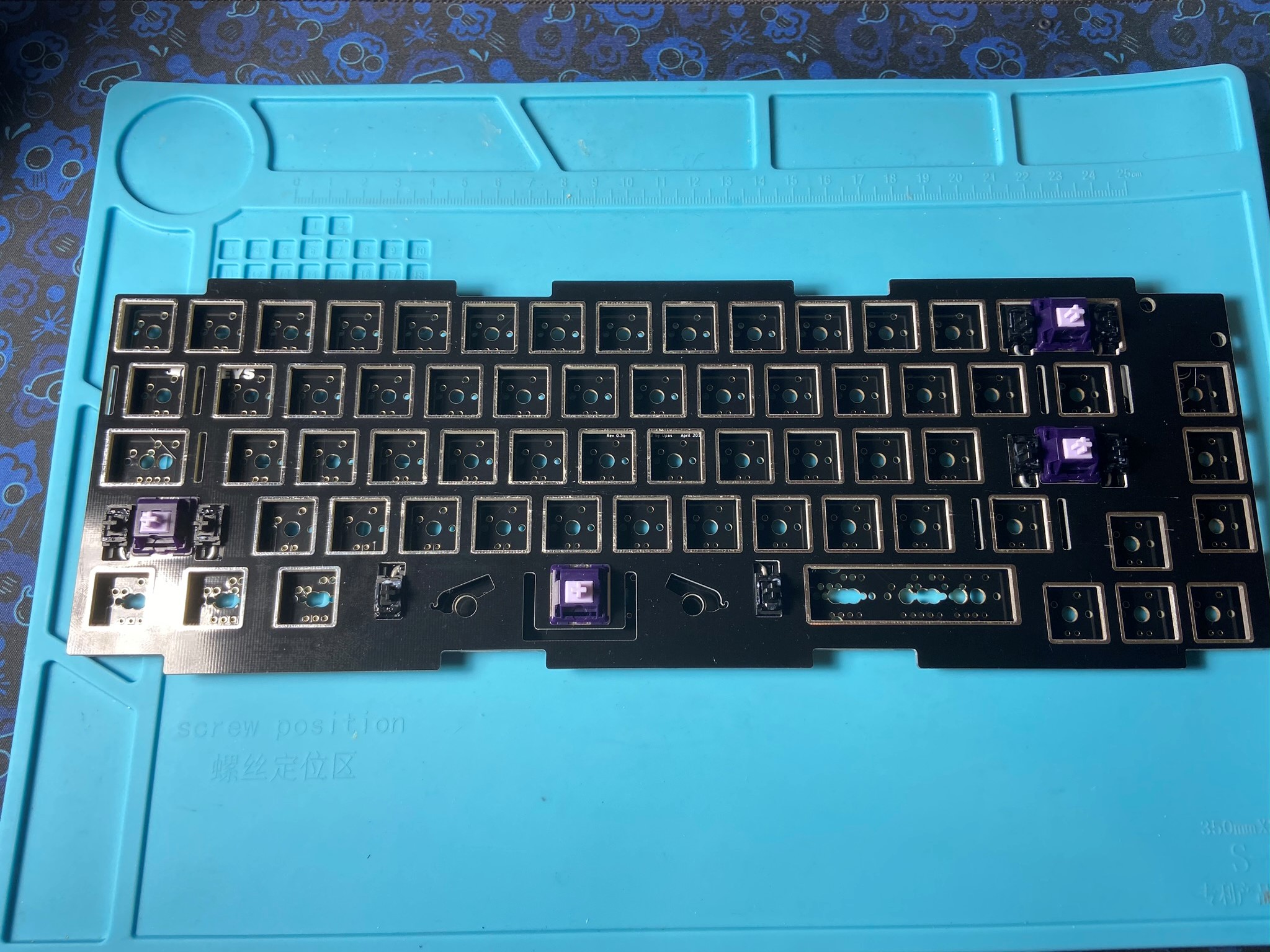
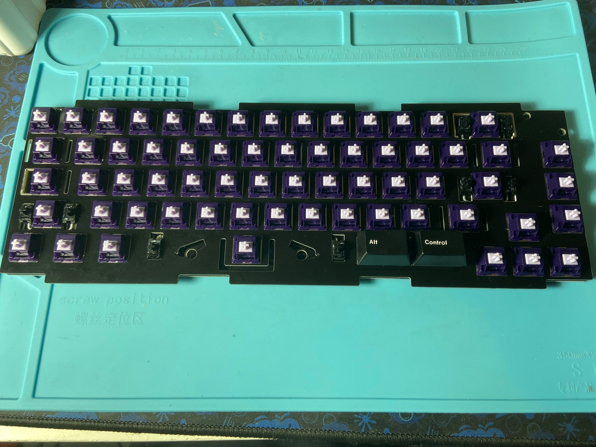
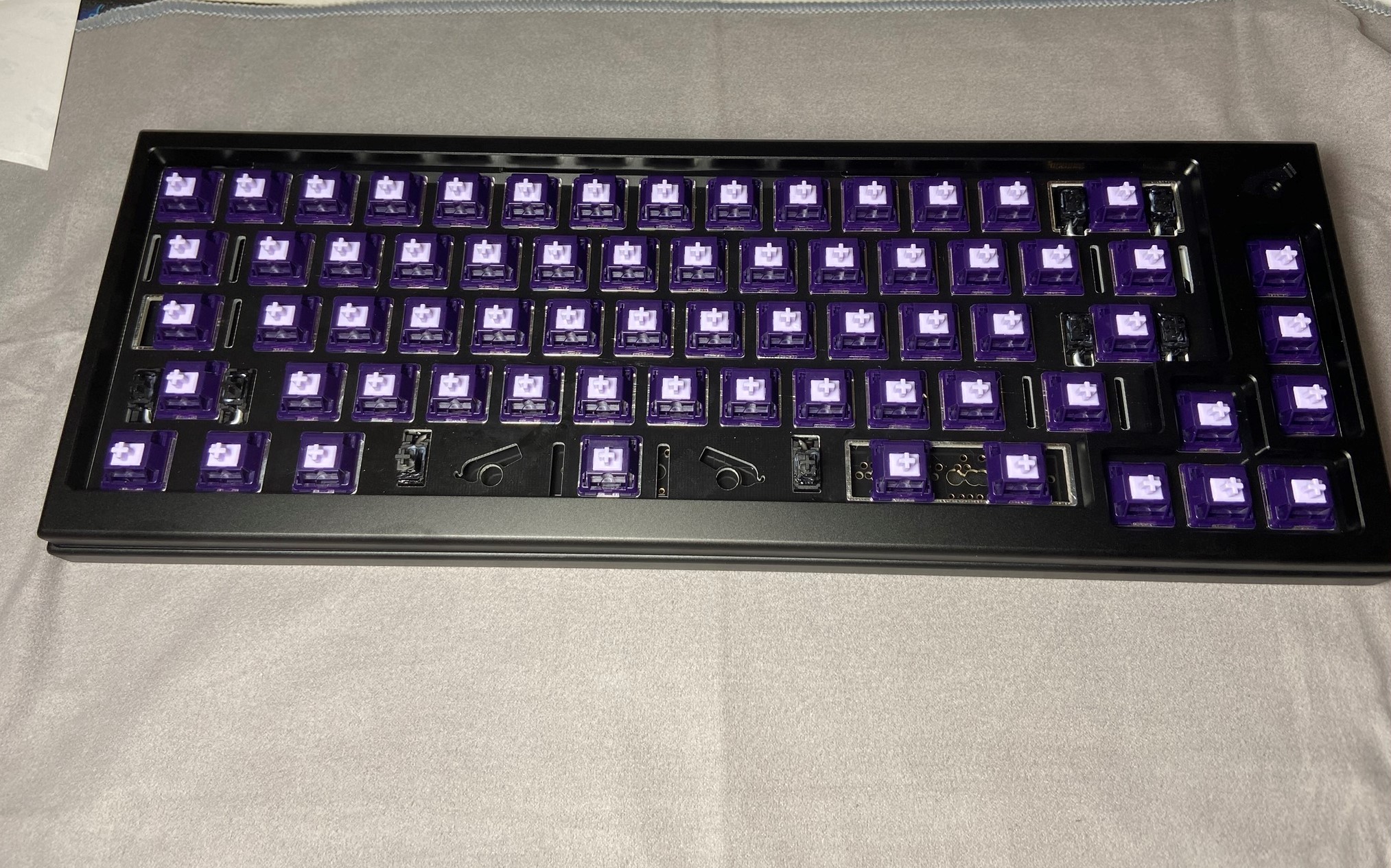
Insert your switches into the plate and PCB, and solder the switch legs into the switch holes. If you're building with a hotswap PCB, make sure to support the bottom of the socket as you insert switches to avoid damaging the PCB. Be sure none of the switch pins are bent, and that the switches are seated all the way flush with the plate:
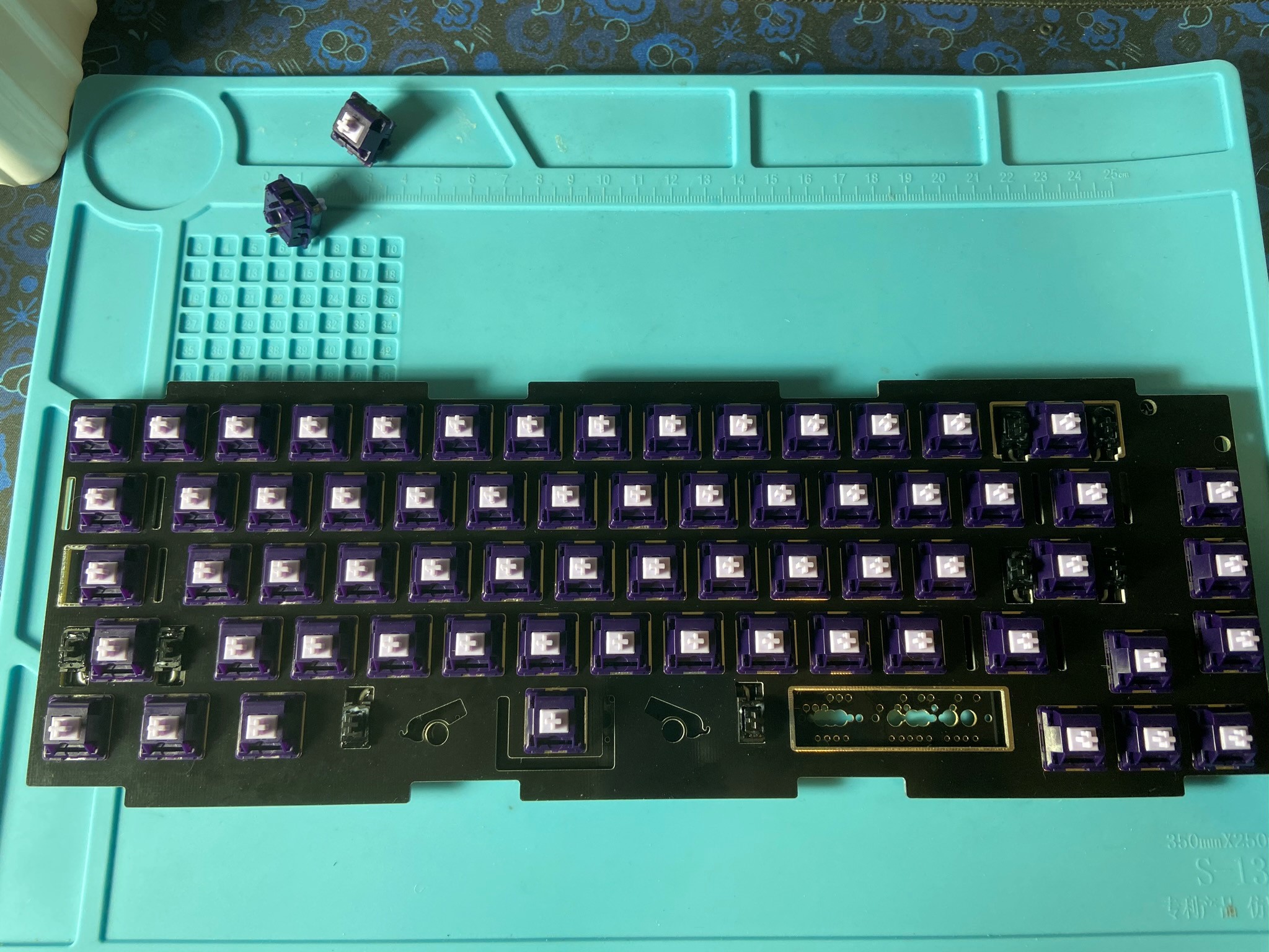
-
Some of the footprints may be tricky - if you're unsure of what footprint to use, feel free to grab some keycaps to help!
-
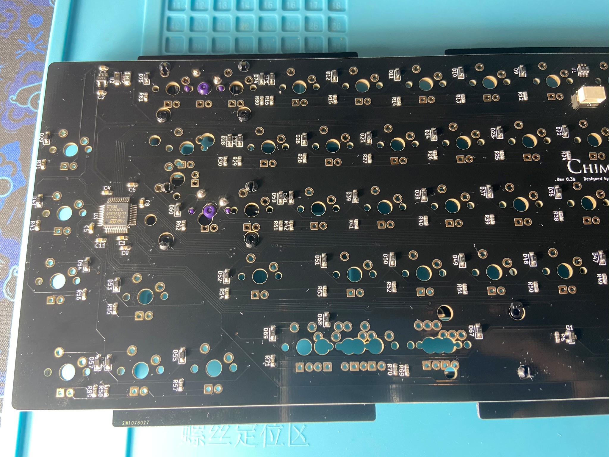
Finish soldering up your PCB
-
Test your soldered PCB
Daughterboard Installation
-
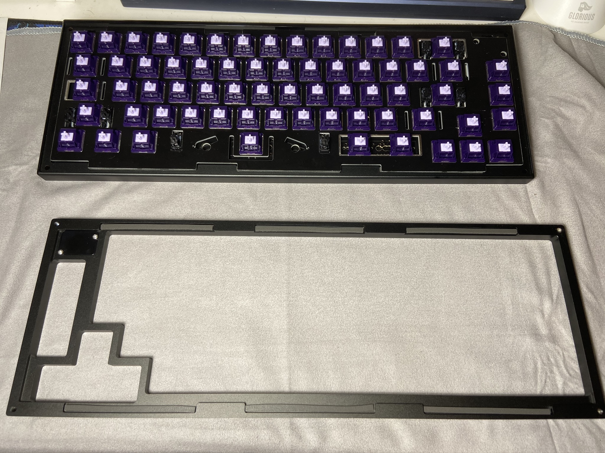
Now we have to disassemble and prepare the case to add the plate and PCB assembly. Begin by unscrewing the case using an M2.5 hex driver (we provided one with each Chimera65)
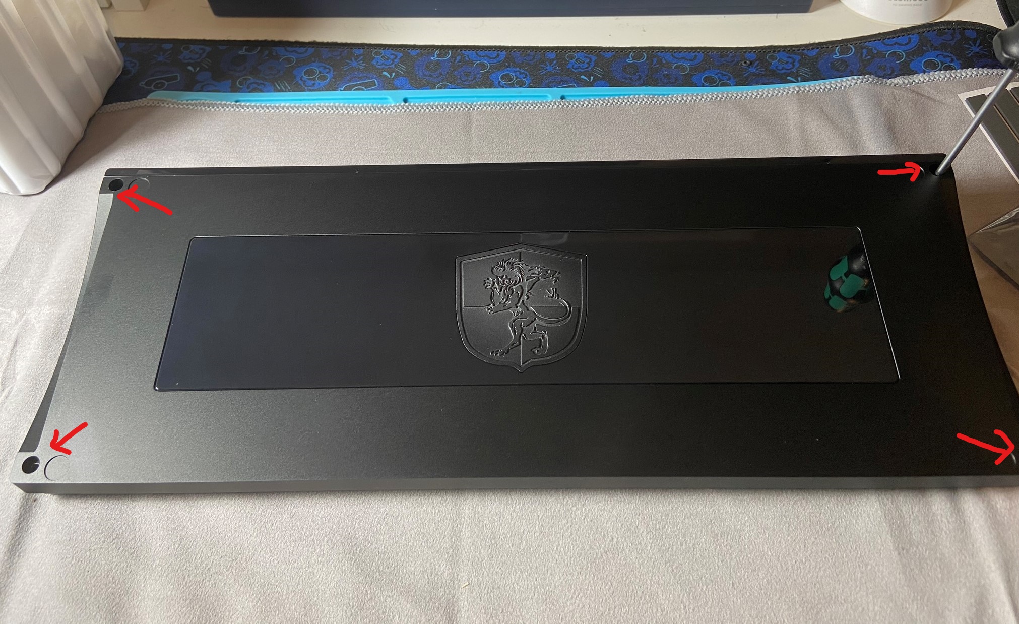
-
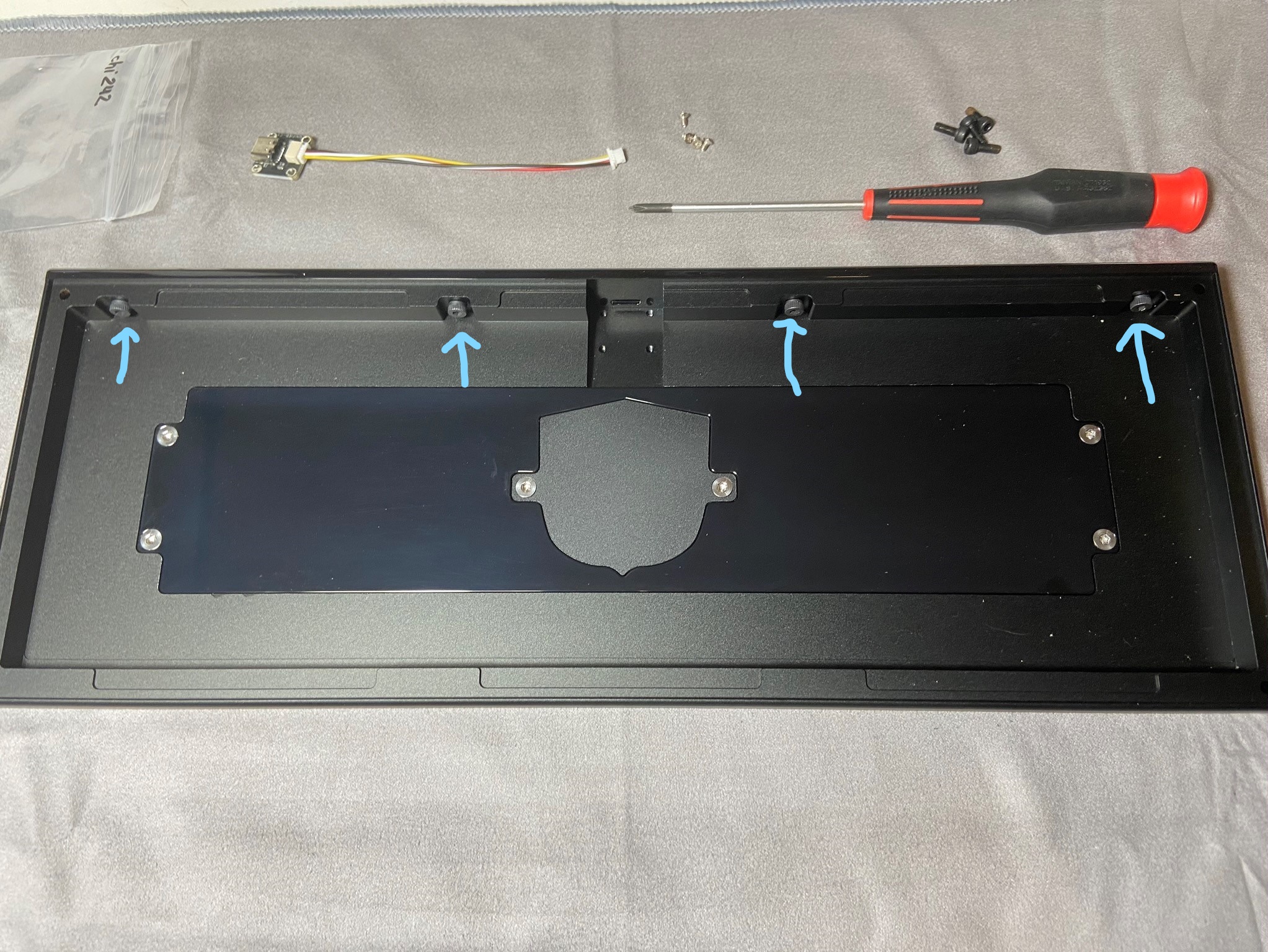
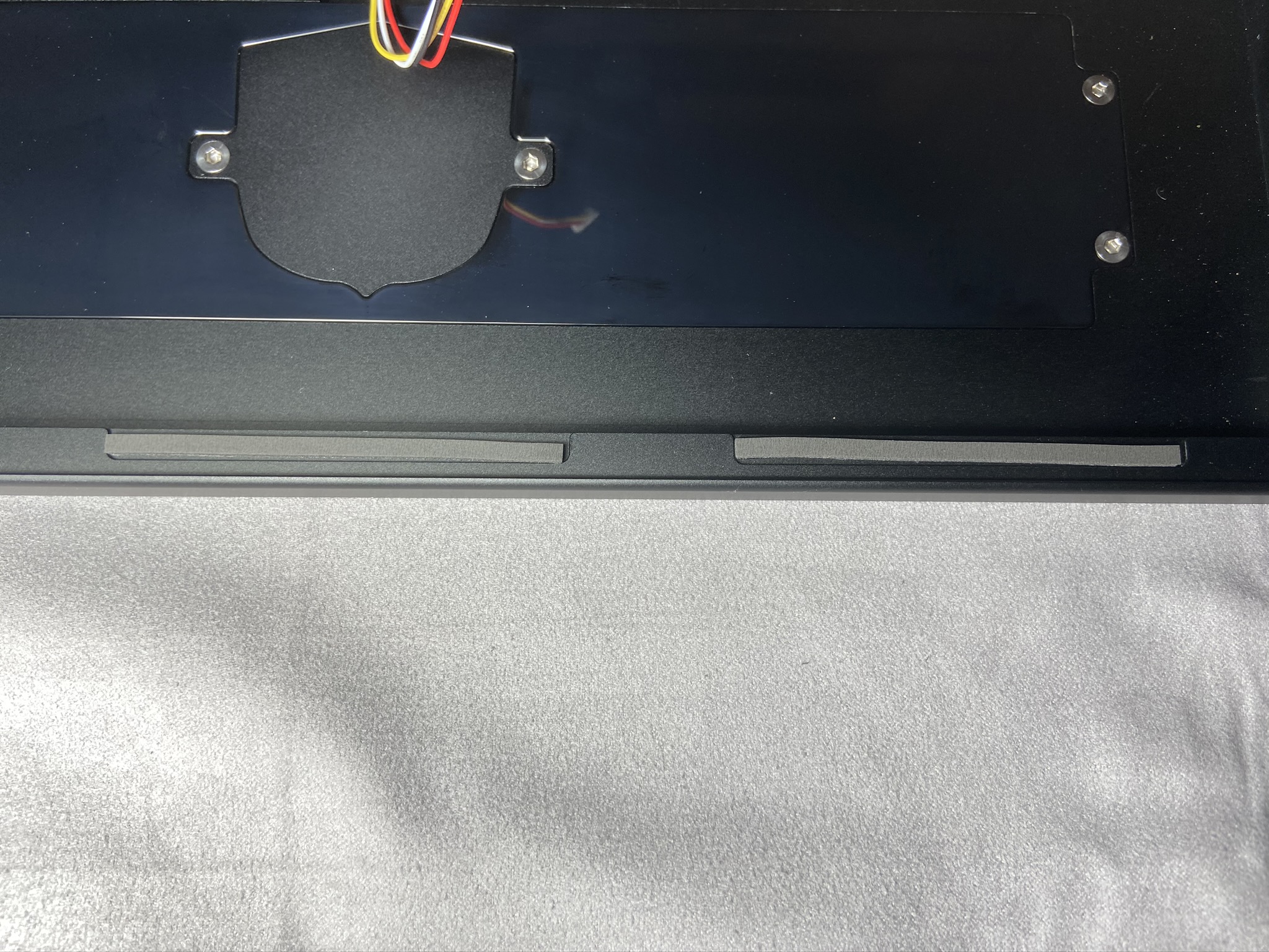
Set the top piece of the case aside. Now we need to remove the back by loosening these screws using a M2.5 Hex Driver.
-
Be careful when unscrewing the back. In this photo below, I made sure my screwdriver did not rub against the case, and also covered it with a cloth to be extra safe. If you're using the included hex key, laying a cloth down will also help keep the case safe as you make your partial rotations.
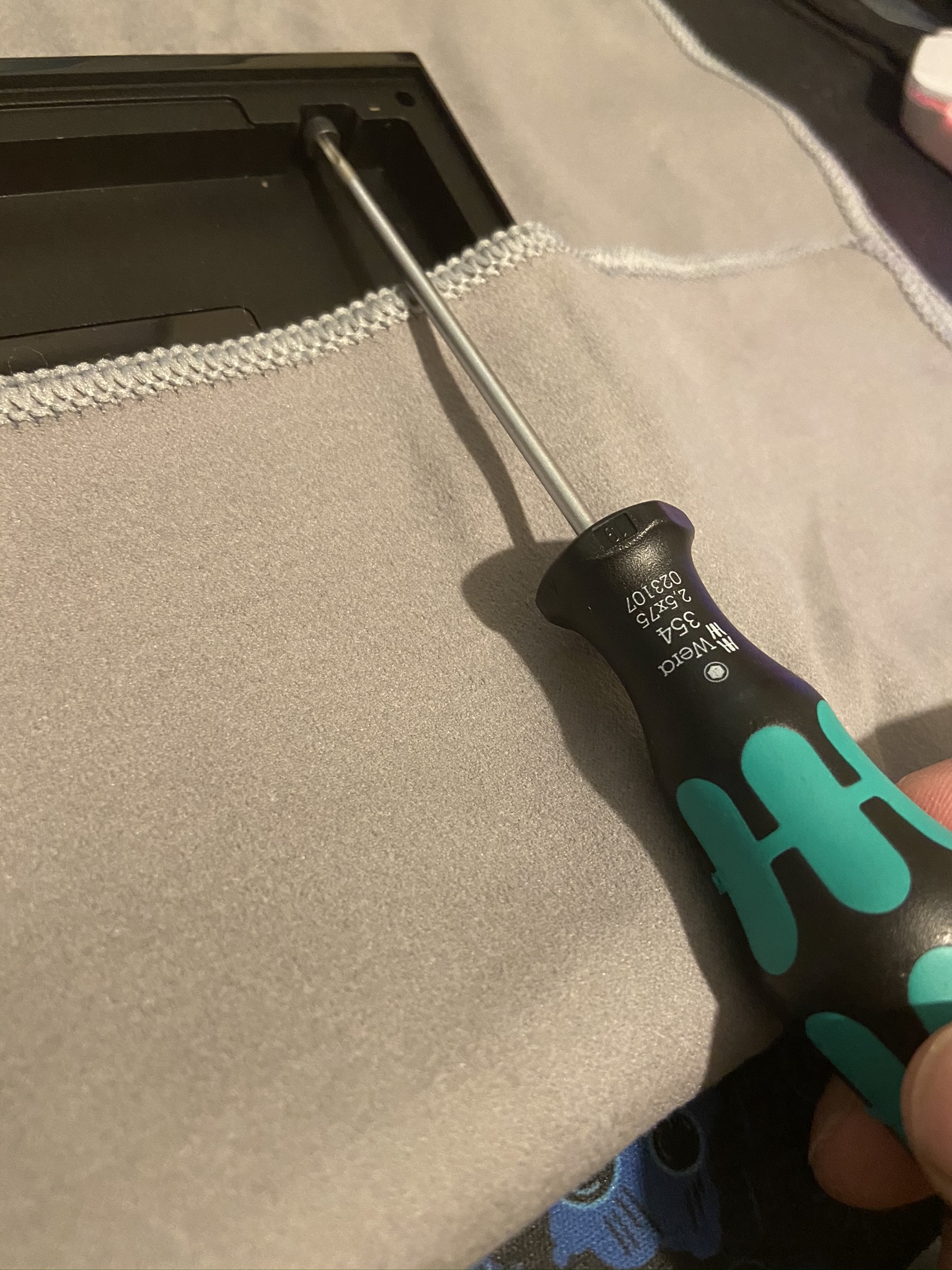
-
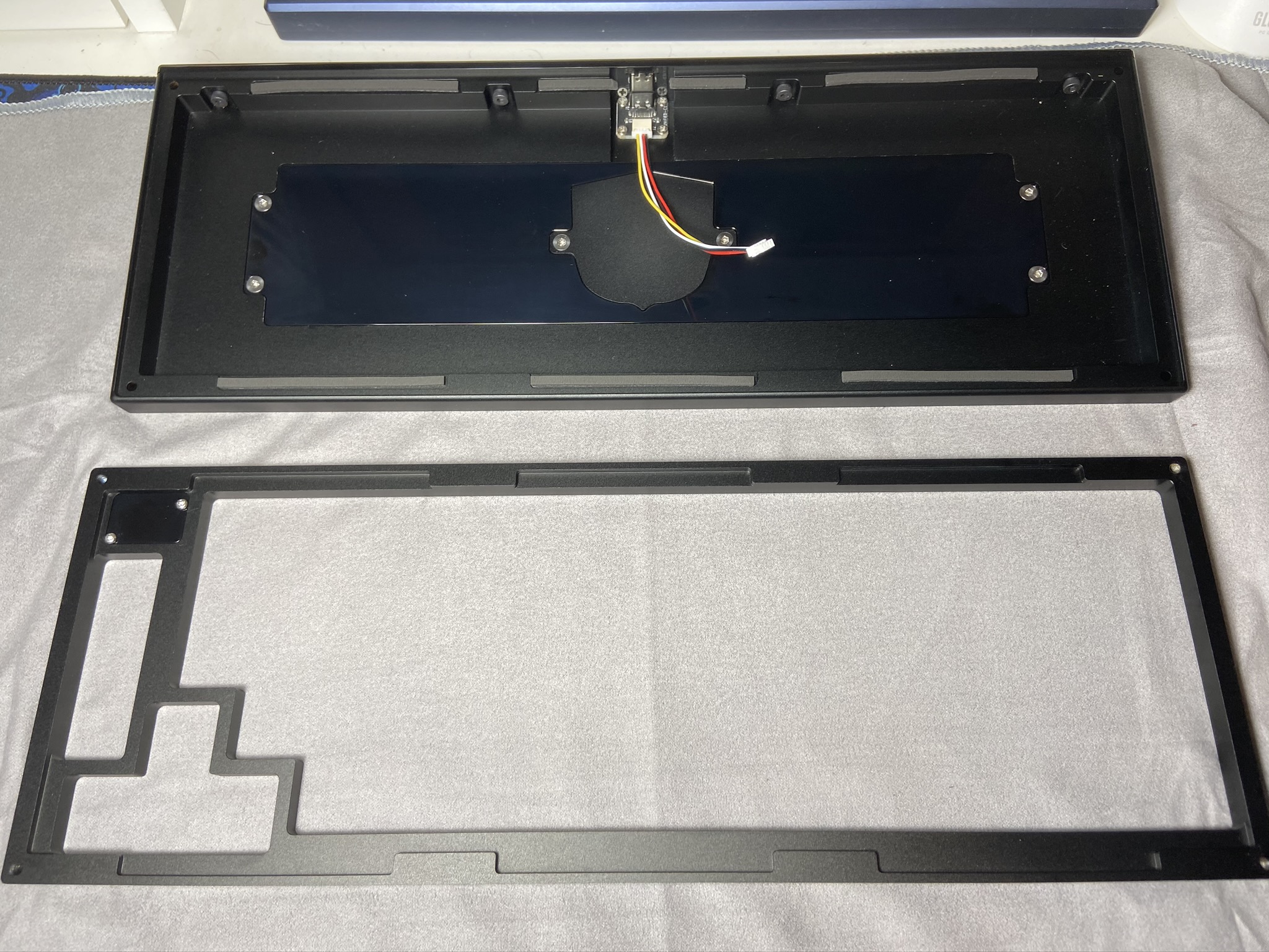
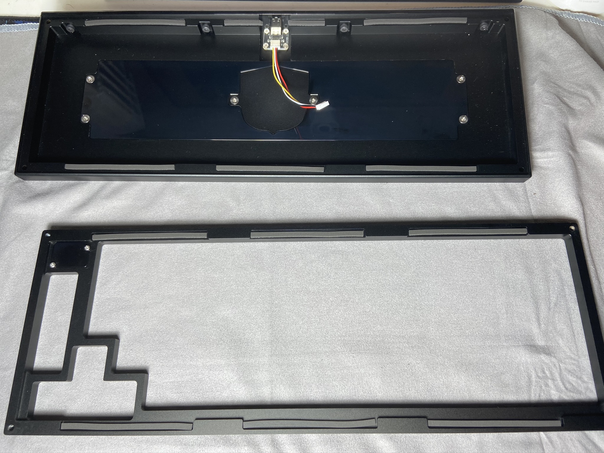
Set the back piece down gently after its been unscrewed
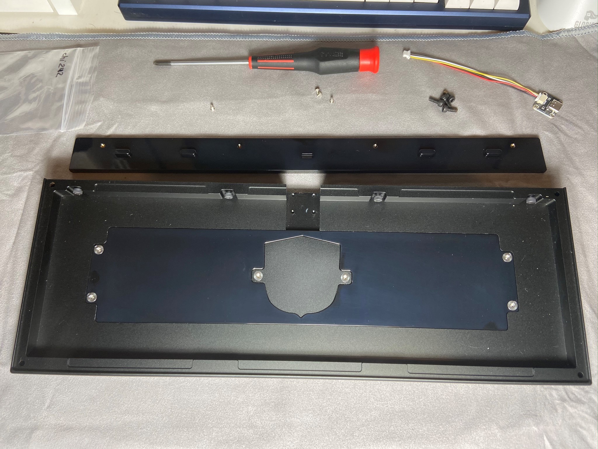
-
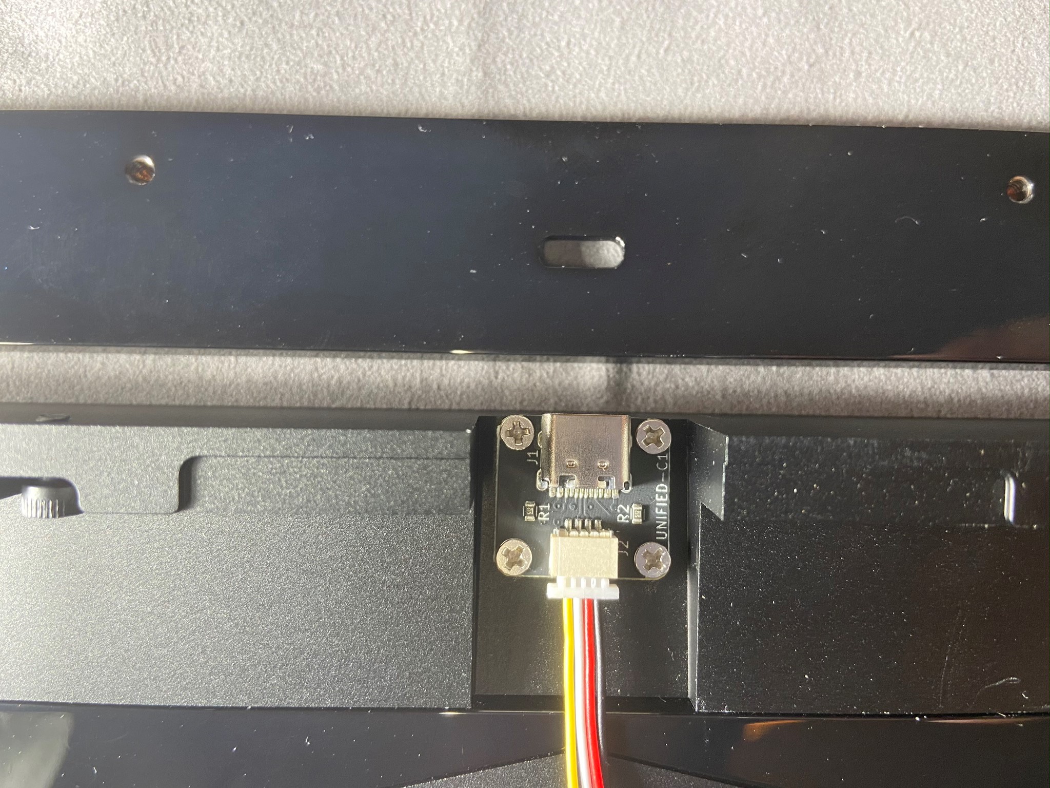
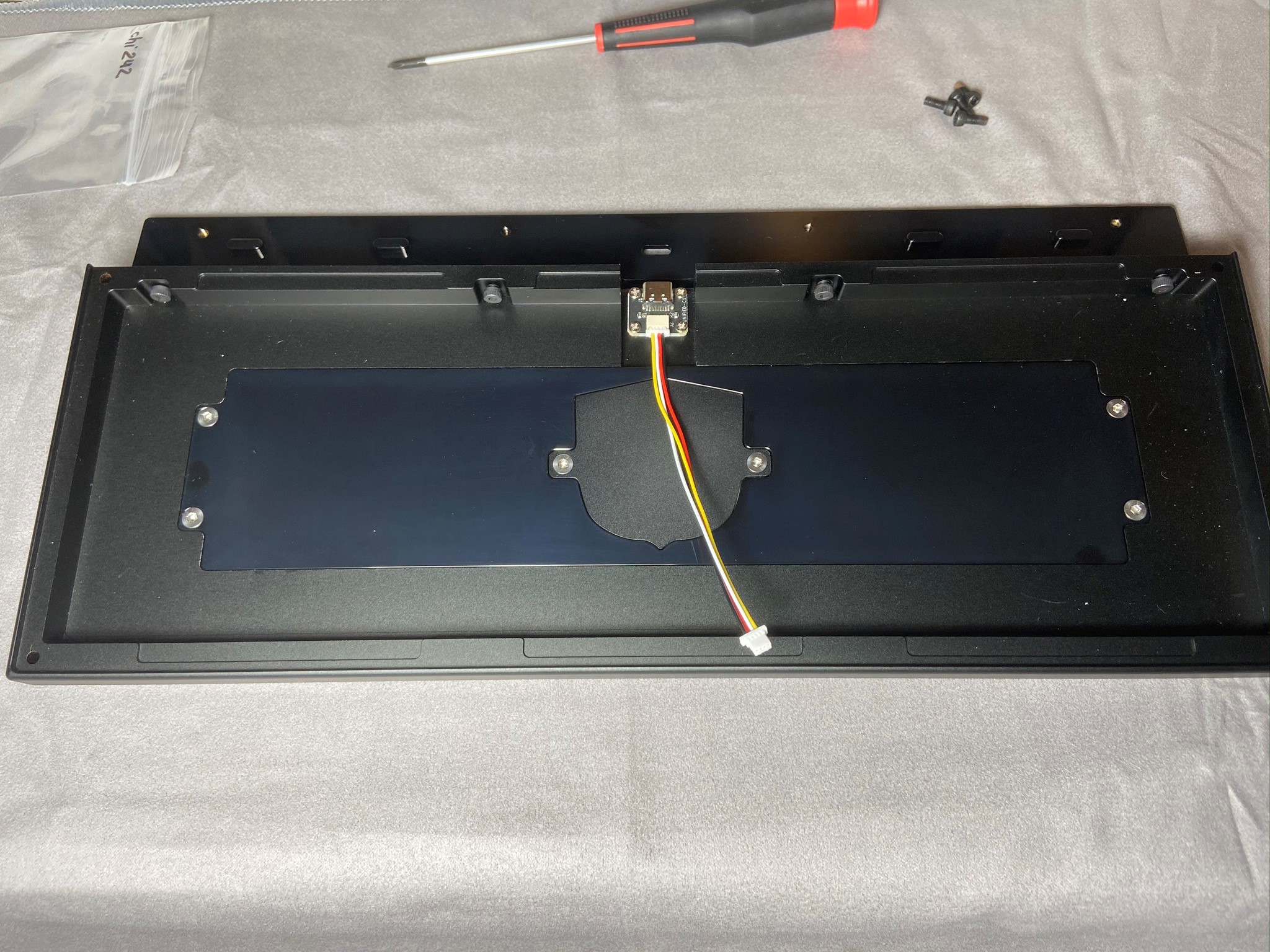
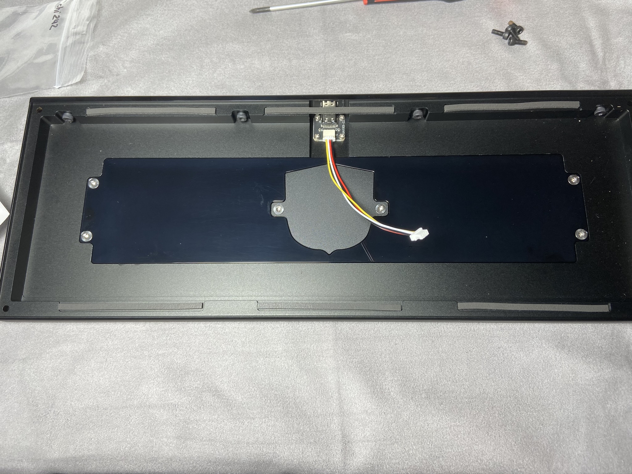
Install the Daughterboard using a Phillips head screwdriver and the included 4 screws.
-
When that's done, it should look like the photo below. Attach the back piece to the bottom again, using the same screws as before.
Gasket Installation
-
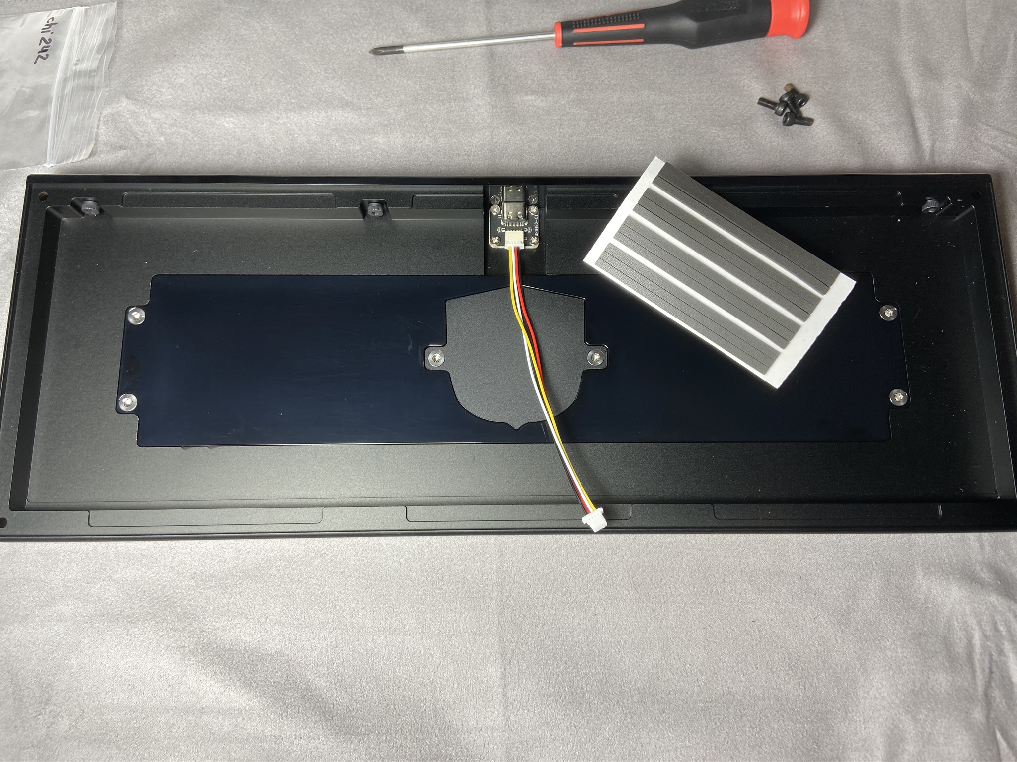
Next, we need to add the poron gaskets to the case. Throughout this process, please remember, the gasket placement does NOT have to be perfect!
-
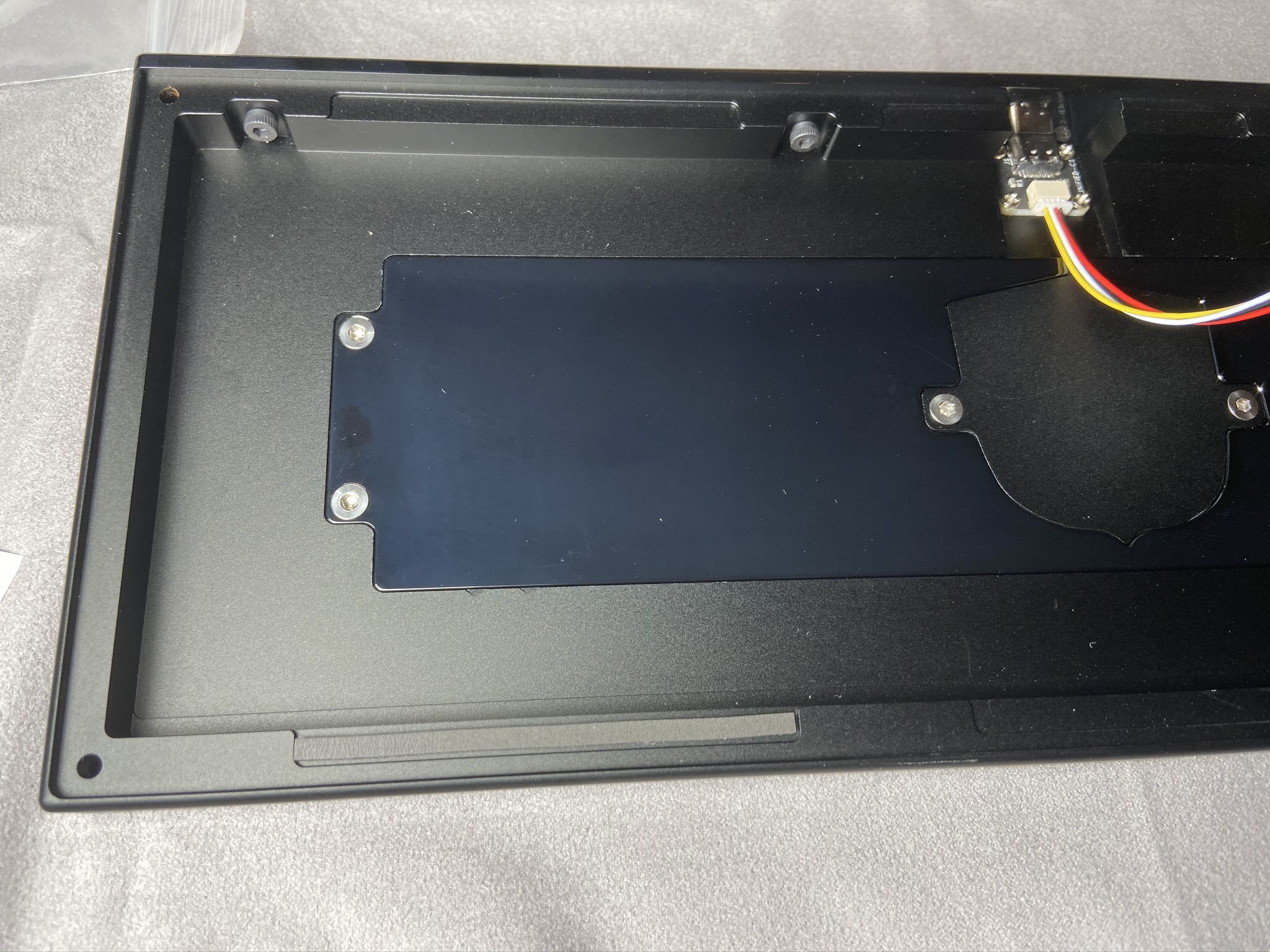
Align one edge of your poron strip with the edge of the gasket indentation on the bottom case. Stick the gasket to the case, making sure you stay within the indentation. It's ok if your gasket doesn't go quite far enough, or is curved, as long as its inside the indentation.
-
As you can see here, the gasket application doesn't have to be perfect. They'll still dampen vibrations and give a nice typing feel.
-
Continue to install the poron gaskets in the bottom part of the case
-
If you want, you can cut the poron strip that spans the daughterboard gap.
-
Repeat the same process for the top
Plate/PCB Installation
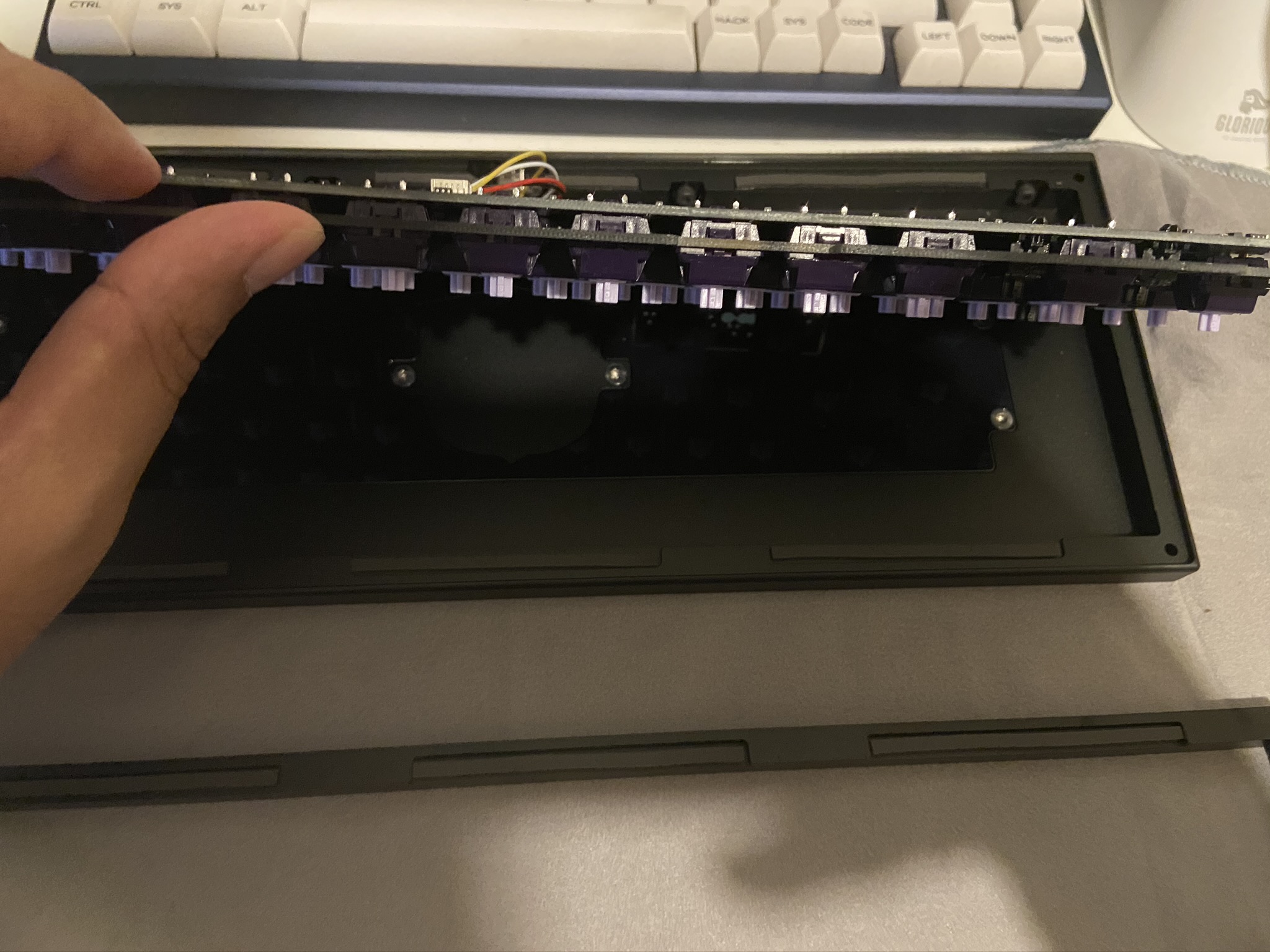
- Plug in the JST cable from the daughterboard into the PCB as shown. Then flip the PCB/Plate assembly backwards into place. You can follow the pictures below to get an idea of how to do it.
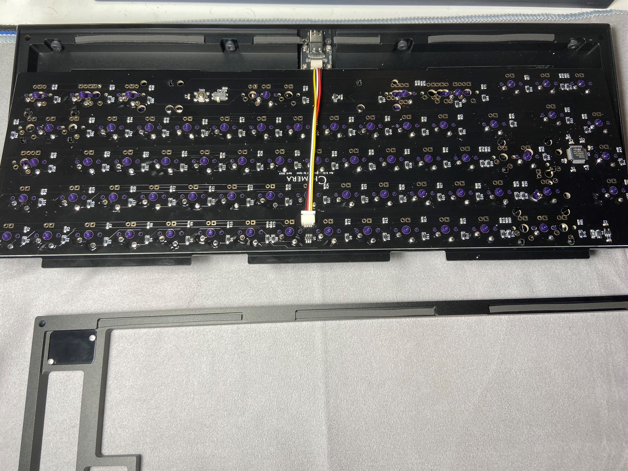
We're now ready to reassemble our case!
Case Reassembly
-
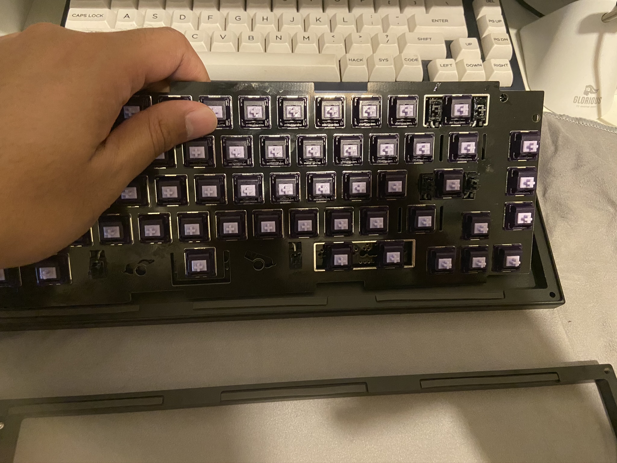
Loosely align the top part of the case above the bottom, on top of the plate. Adjust the plate to be centered.
-
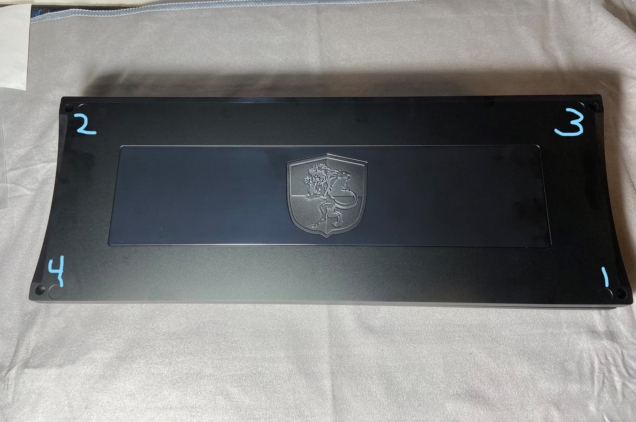
Flip the board to access the screw holes on the bottom. Use a little bit of force to compress the bottom and top together - you'll have to press down to get the gaskets to compress. Start screwing in the screws little by little, following the following photo. Only do a few turns of your screwdriver at a time. This will ensure we get even compression across the gaskets. If you're building a PC unit, start by partially screwing in the corners in the same order seen below, then install the the middle four using the same logic.
-
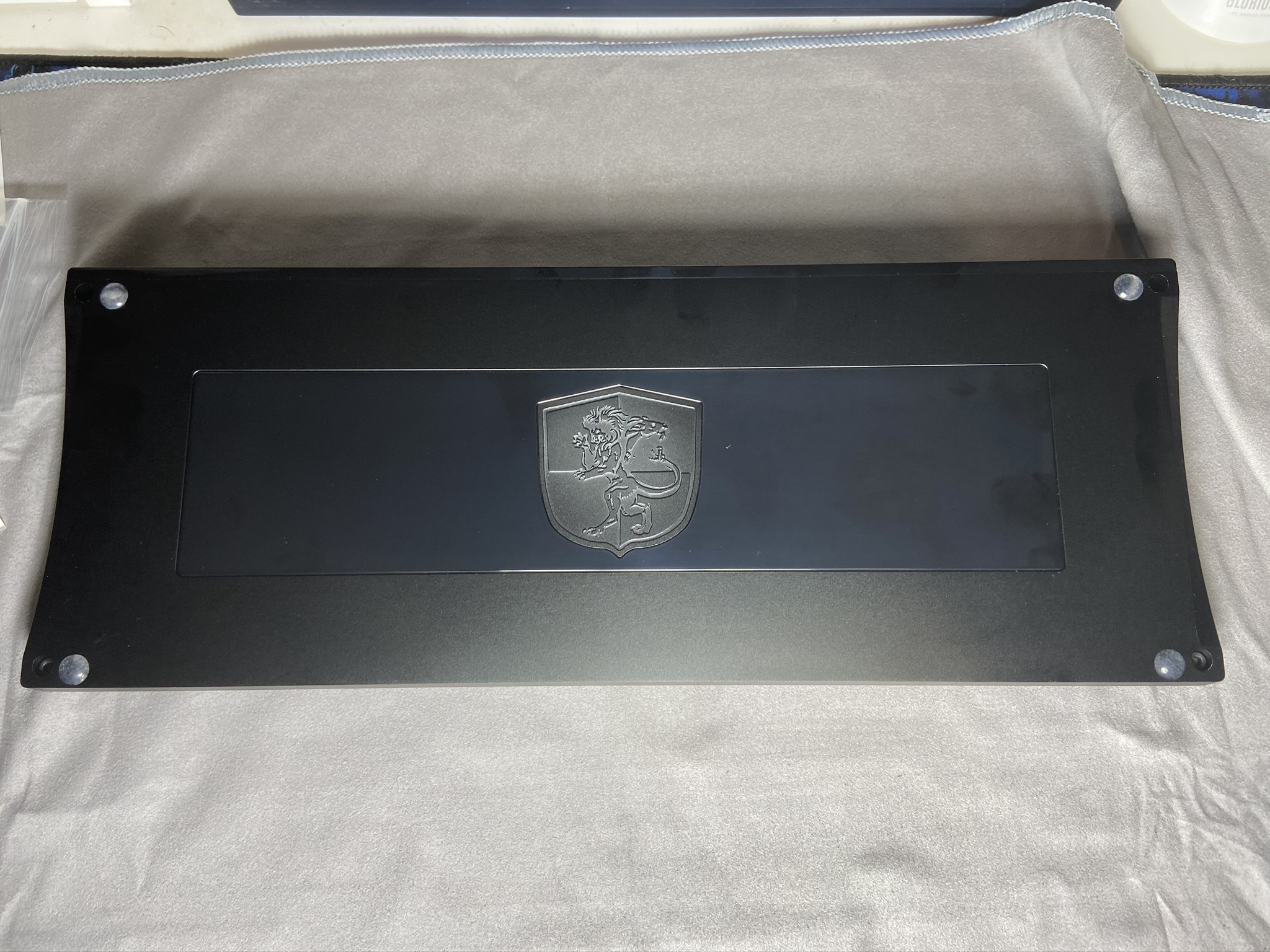
Finally, install the bumpons:
Final Touches
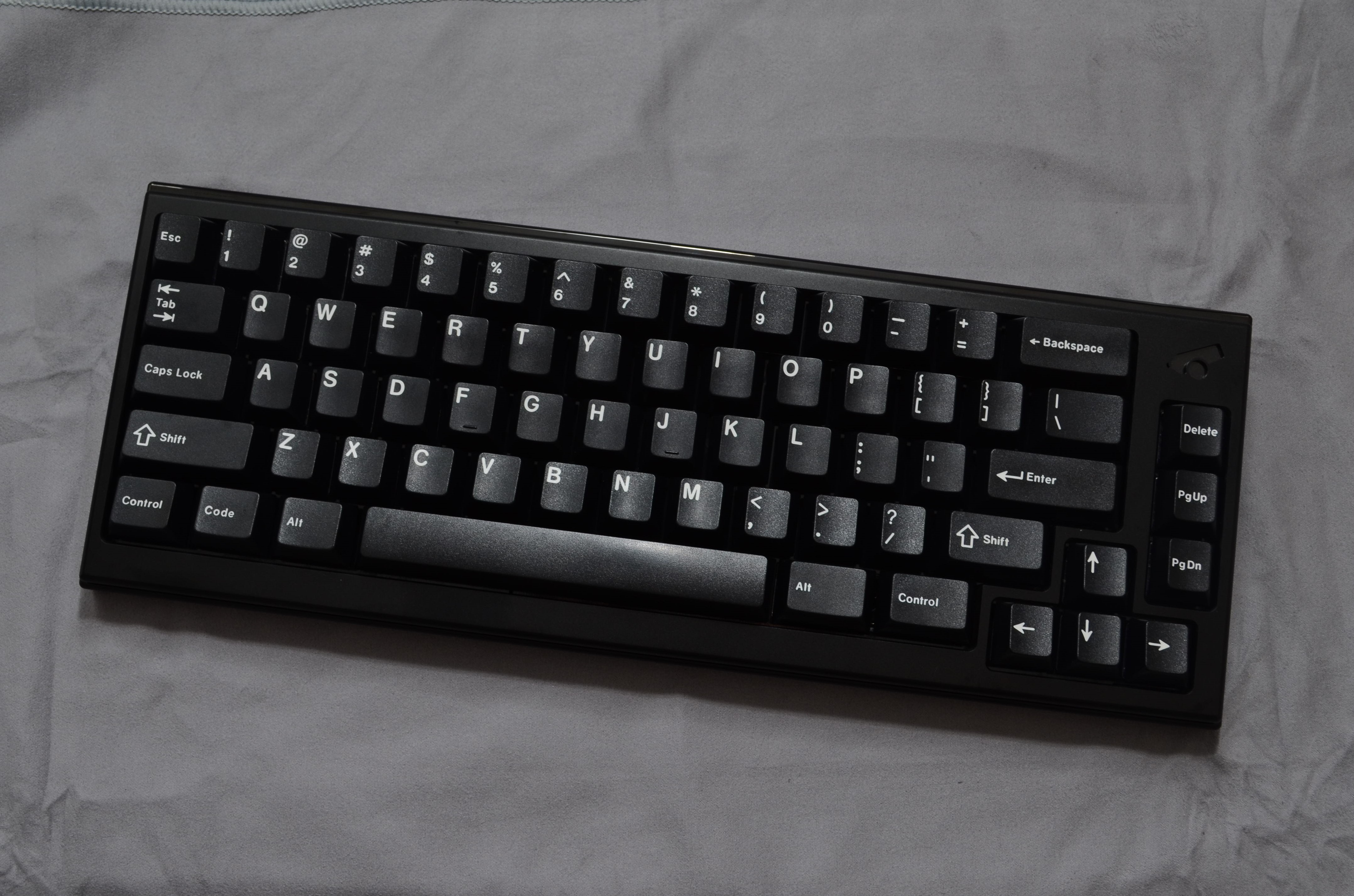
- Flip your keyboard back over, and enjoy!