Sat75 X Build Guide
This guide will walk you through the building process of your brand new Sat75 X Keyboard! If you run into any issues not covered by this guide, our Satisfaction75 user guide or our PCB Troubleshooting guide, be sure to reach out to our support team via the widget found in the bottom right corner of our contact us page.
Getting Started
Before starting the build, make sure you have everything you need to build. Please note that this build guide was created with a prototype unit, which might have some parts that look slightly different. While building your Sat75 X, it is highly recommended to build on an anti-static surface and grounding yourself to help avoid static shock.
In the box
- Sat75 X top and bottom case with gasket chips and gaskets installed
- Hotswap PCB with 2 standoffs installed
- Knob
- PC Plate
- Hotswap OLED screen
- 4x Clear silicone feet
- Switch and keycap puller
- 3x 2u and 1x 6.25u cherry clip-in stabilizers
- 12x screws
- USB-C cable
- Carrying case
If you're missing anything, let our support team know!
Building a Sat75 X
Preparing and testing the PCB
In order to test the PCB, you need to install the OLED screen. Without it, the keyboard will not function properly. Once the OLED is installed, you can then test the PCB for functionality.
-
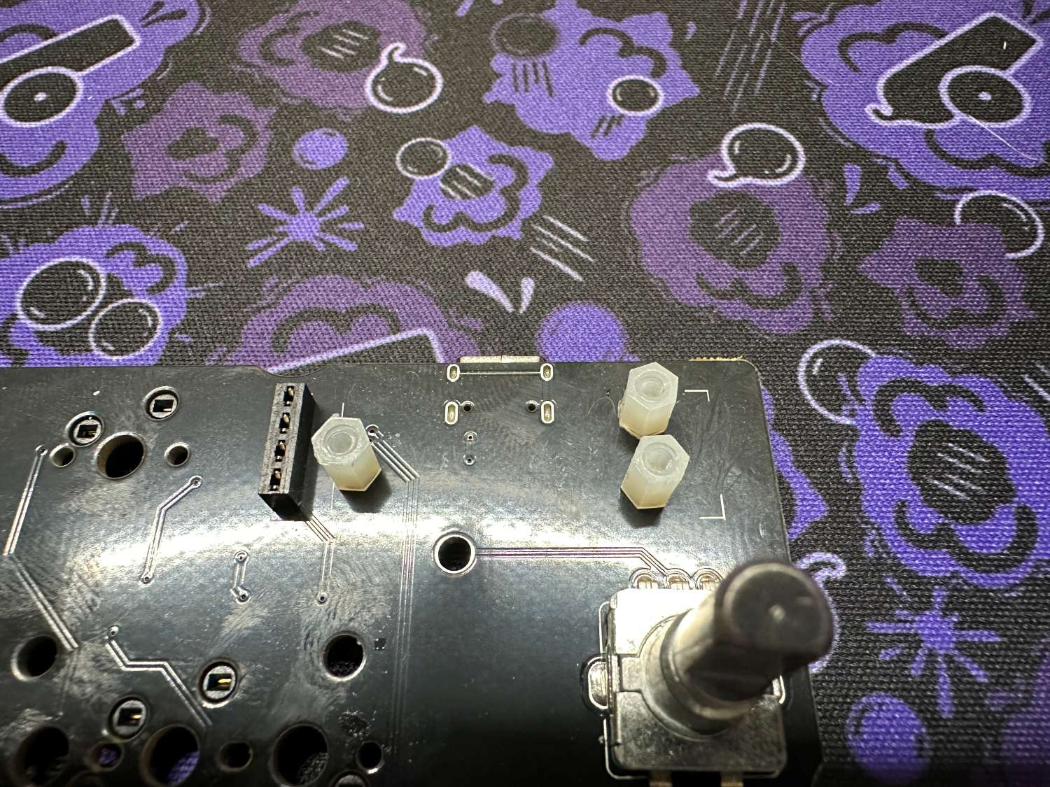
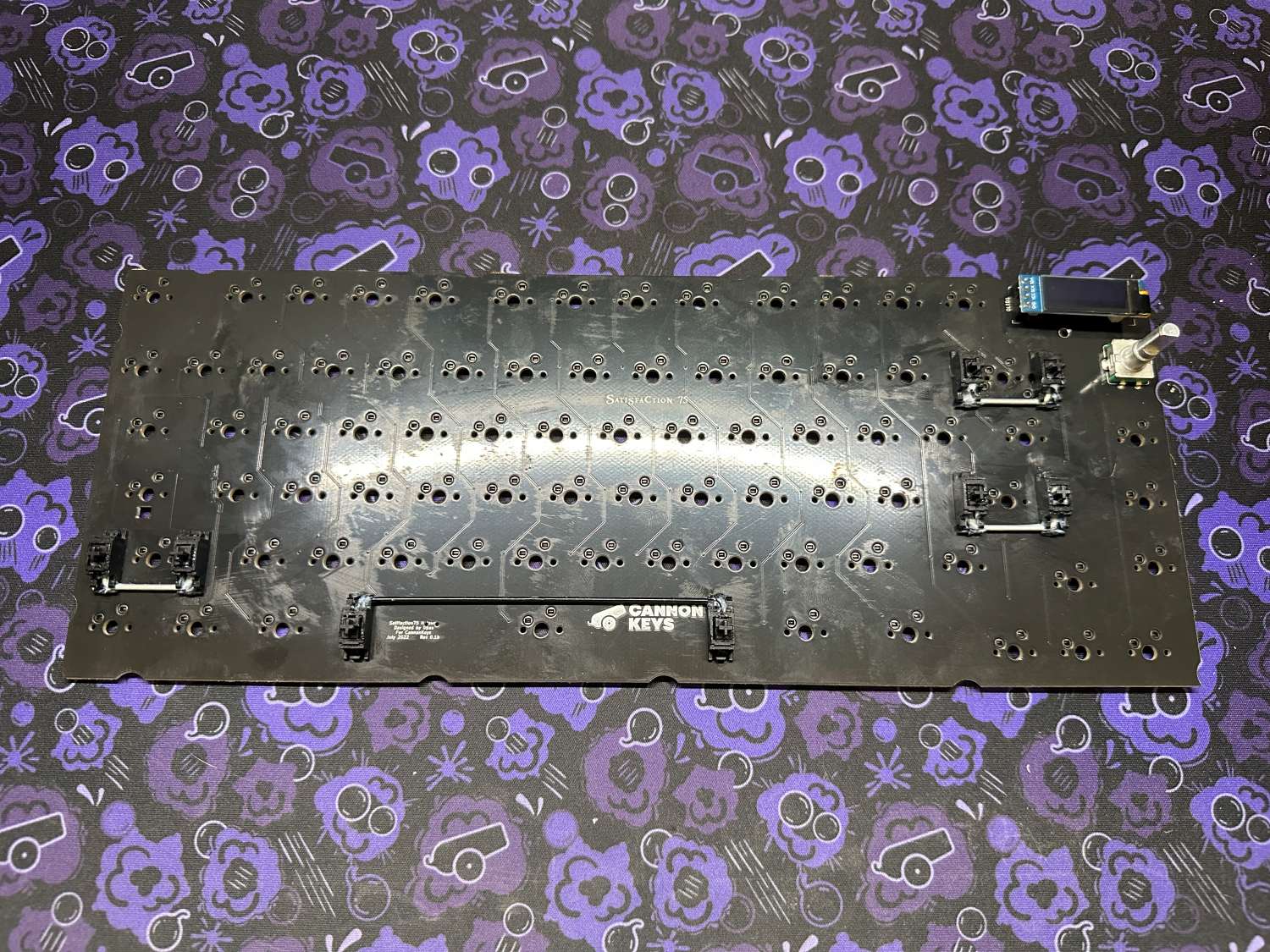
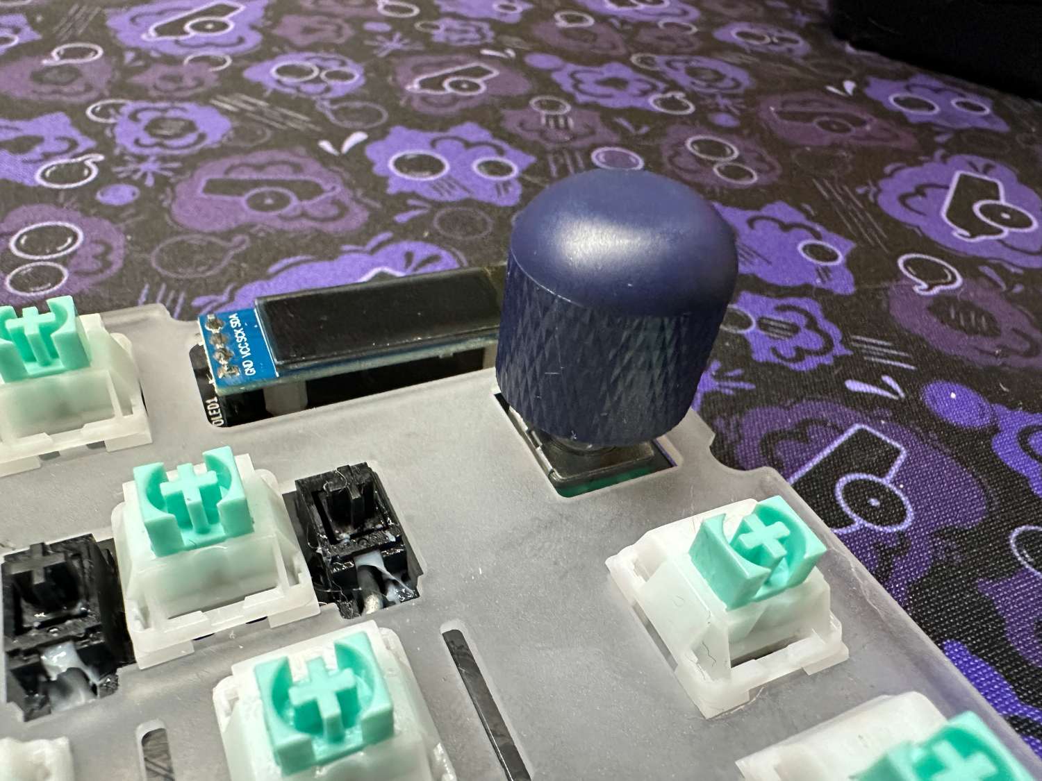
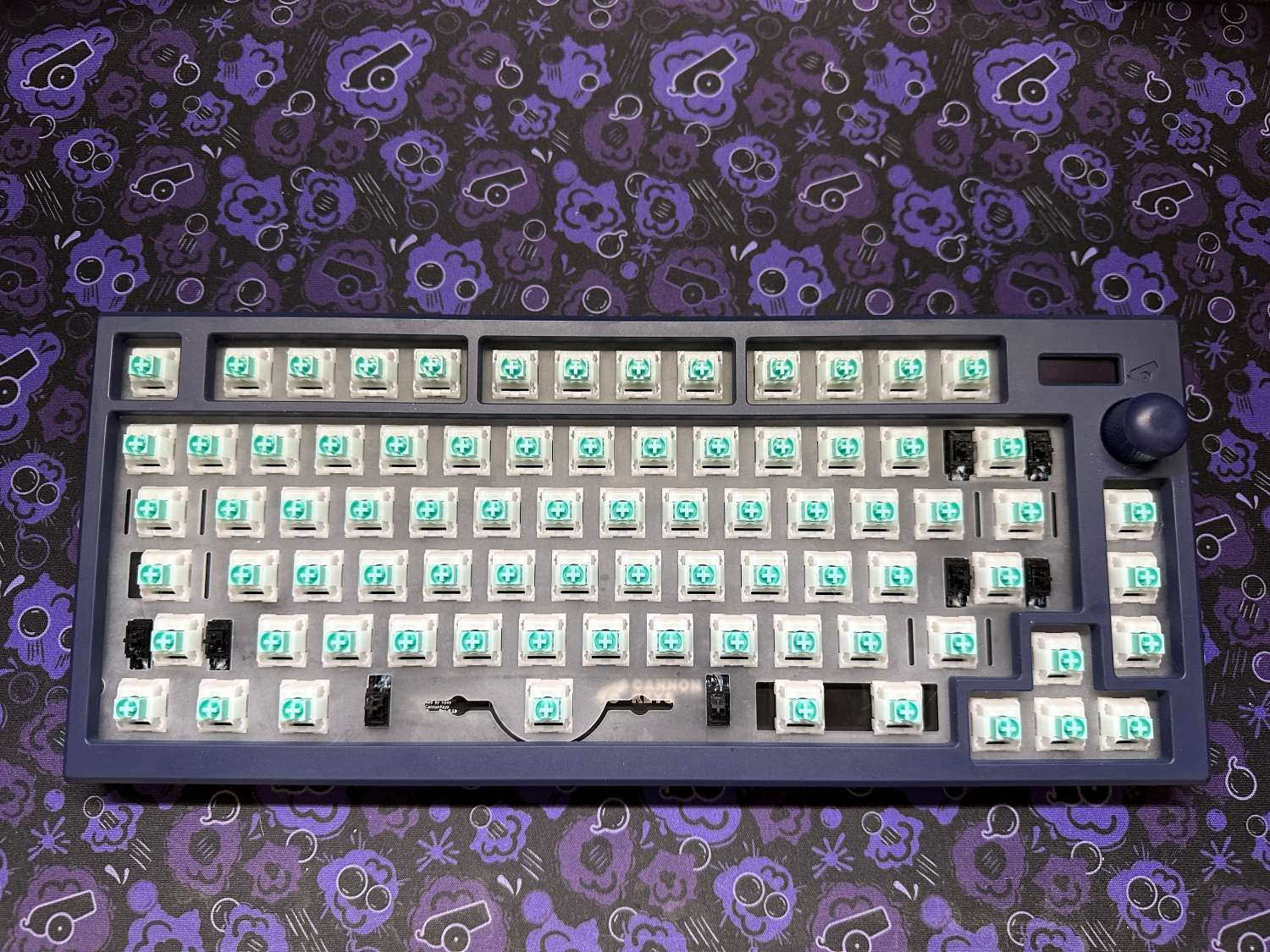
Lay the Sat75 X PCB on a flat surface and locate the 2 nylon standoffs on the top right of the PCB. Please note that while the prototype pictured below has 3 standoffs, production units will only have 2.
-
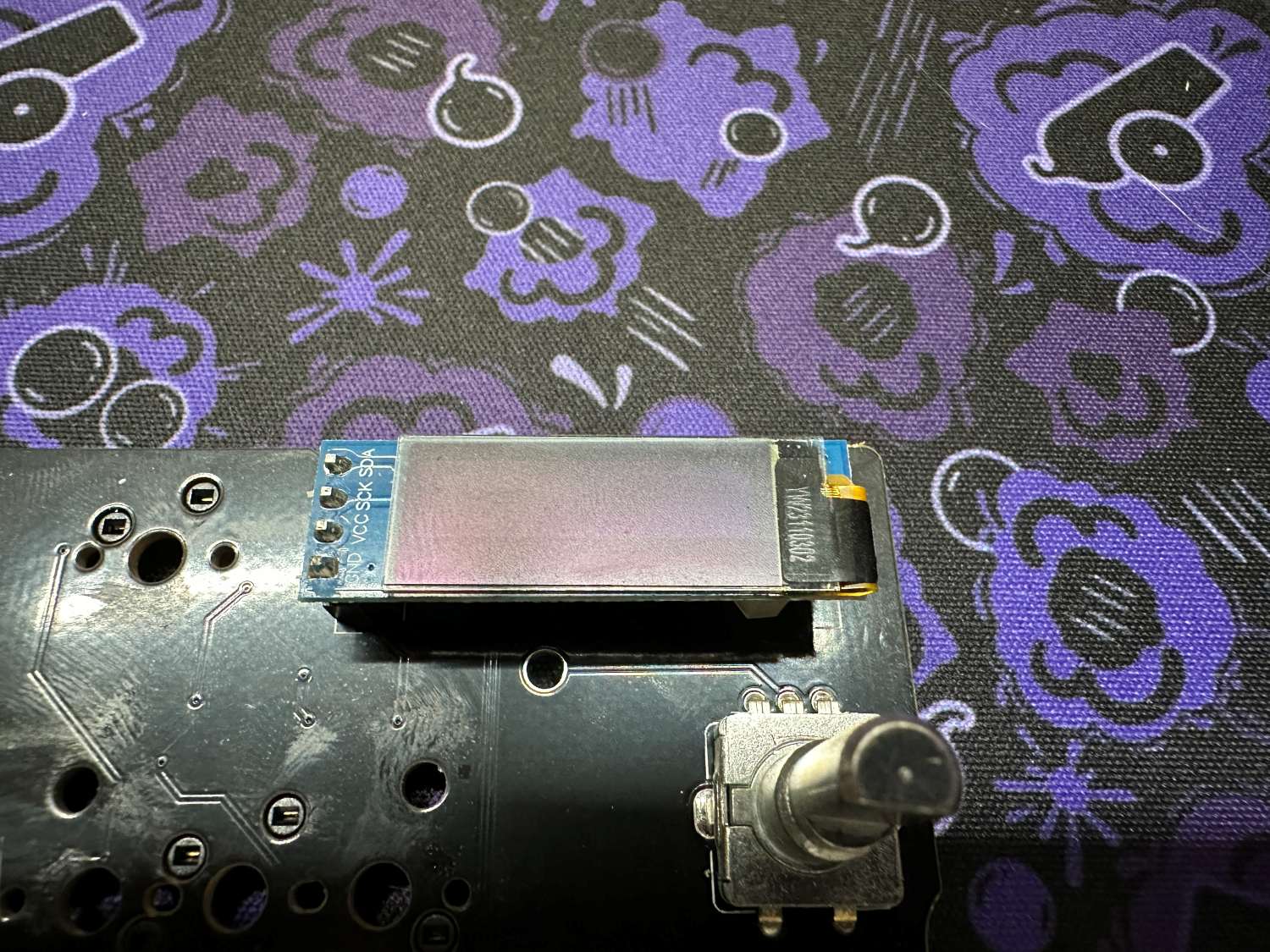
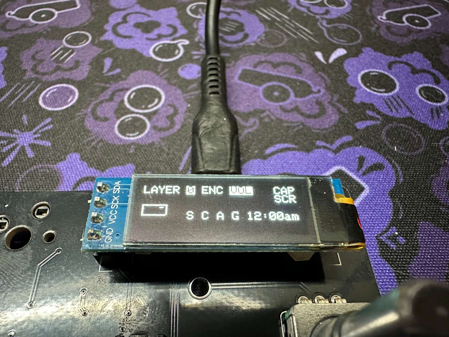
Confirm that the pins on your OLED are straight, then gently install the OLED by pushing the pins into the header. You may want to pull it up slightly after fully seating to get it to sit level. Once installed, plug in your Sat75 X using a USB-C to USB-A cable. You should see the OLED light up. If it does not light up, try reseating the OLED screen. Once installed, you may remove the screen protector on the screen.
-
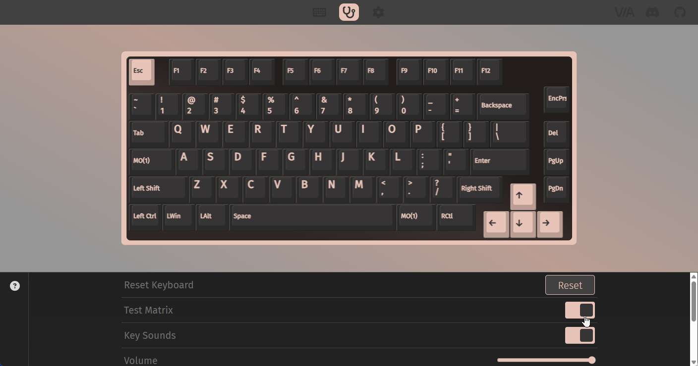
Now that the OLED is installed and the PCB is plugged in, you need to test the keys. To test the keys, please navigate to usevia.app/test in a chromium browser (like Google Chrome), and connect your Sat75 X.
-
Once connected, navigate to the key tester tab. Toggle the test matrix button in the interface.
-
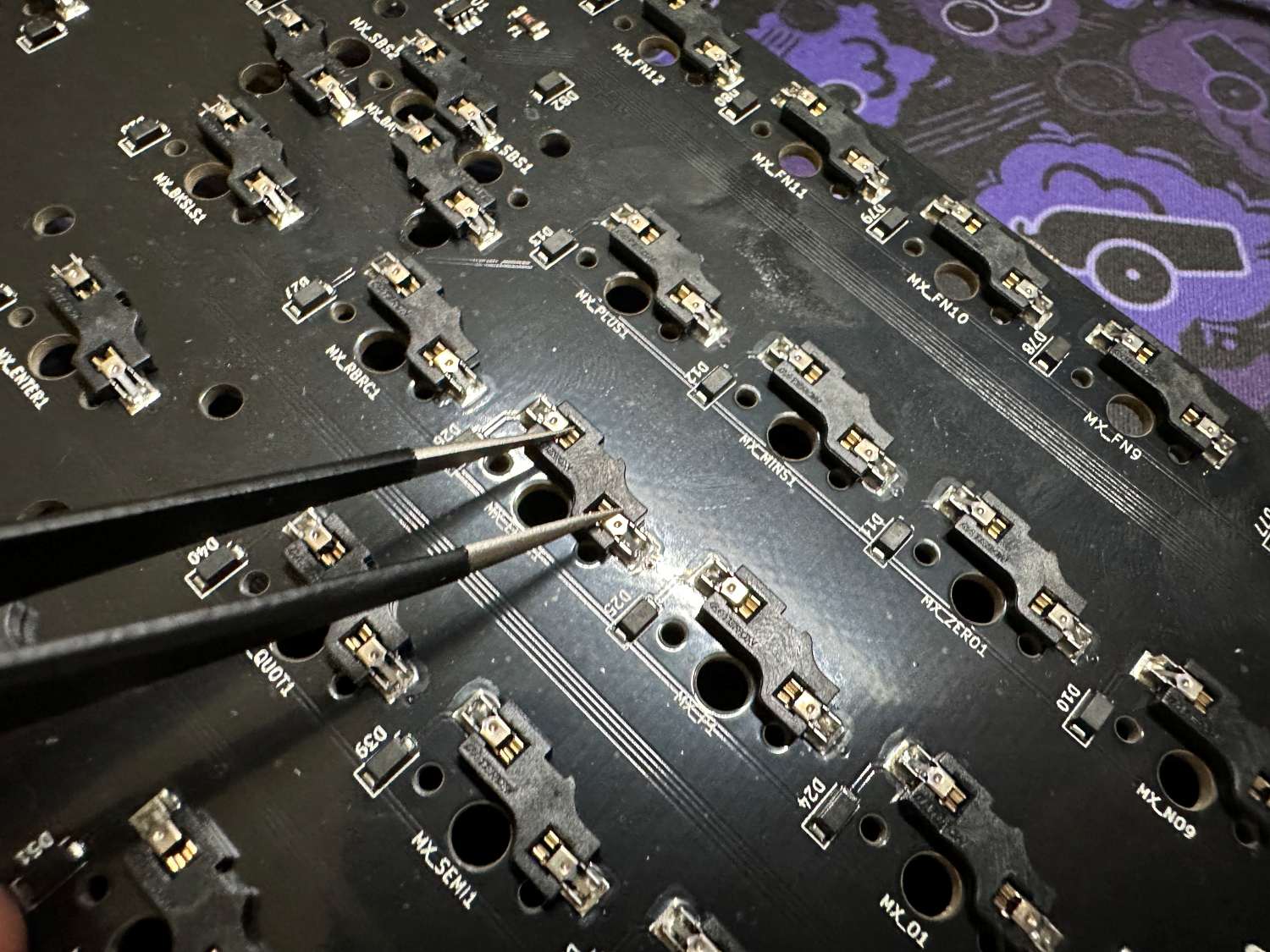
Using tweezers, bridge the metal pads on the underside of the hotswap sockets to test each switch. If you don't have tweezers, other metal objects such as a bent paperclip or a bit of wire can work. Once you've confirmed each socket is working, you can continue into the next section.
PCB & plate assembly
Now that you have confirmed the PCB is functioning properly, you can unplug the PCB and continue with the build!
-
Assemble your stabilizers, and install them into the PCB. If you're using the included cherry clip-in stabilizers, we recommend lubing and clipping them - here is a great video on that. If you need some quick tips on putting the stabilizers together, we have some additional information here.
-
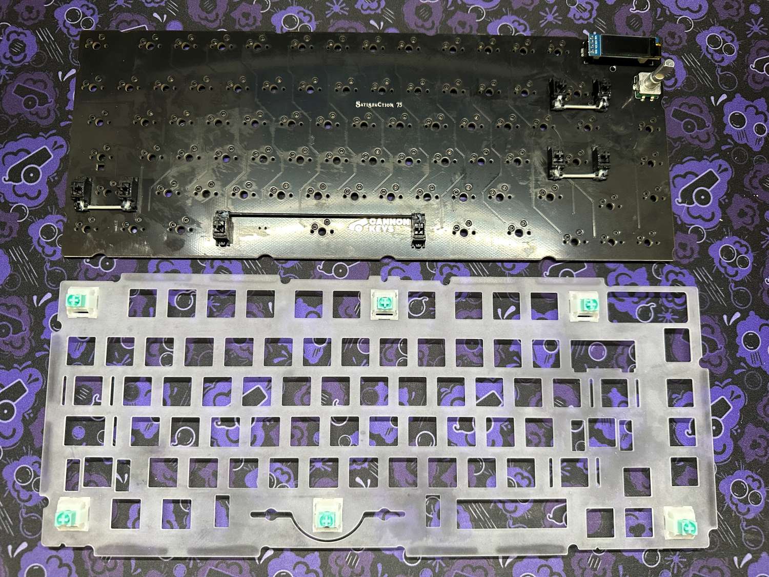
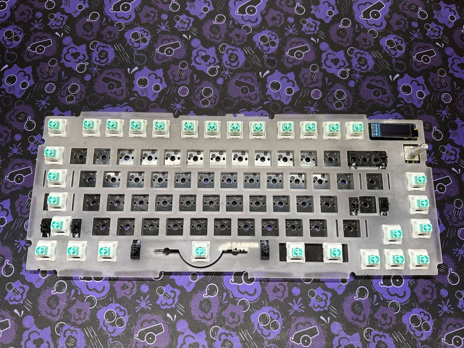
Next up you need to put the switches into the plate and PCB. In this guide we'll go over some tips that should make this process quick and easy! As a general note while doing this, it is very important to always support the backside of the socket while installing switches. If you're using plate foam, lay it on the PCB now before you begin adding switches. Start by inserting switches into the outside and corners. These will help give support while you install the rest of the switches.
-
Line up the plate over the PCB, and start pushing the switches in one by one. Use the video below for a tip on doing this safely and smoothly.

-
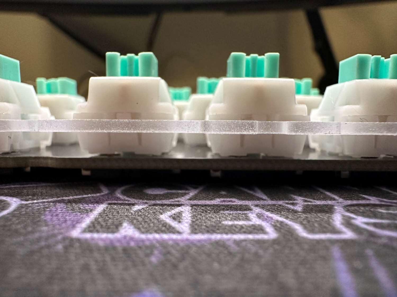
Next, finish up installing switches around the outside. With the outer ring complete, the rest of the switches should be easier to install! Before continuing on, check that there is an even gap between the plate and PCB around the entire assembly.
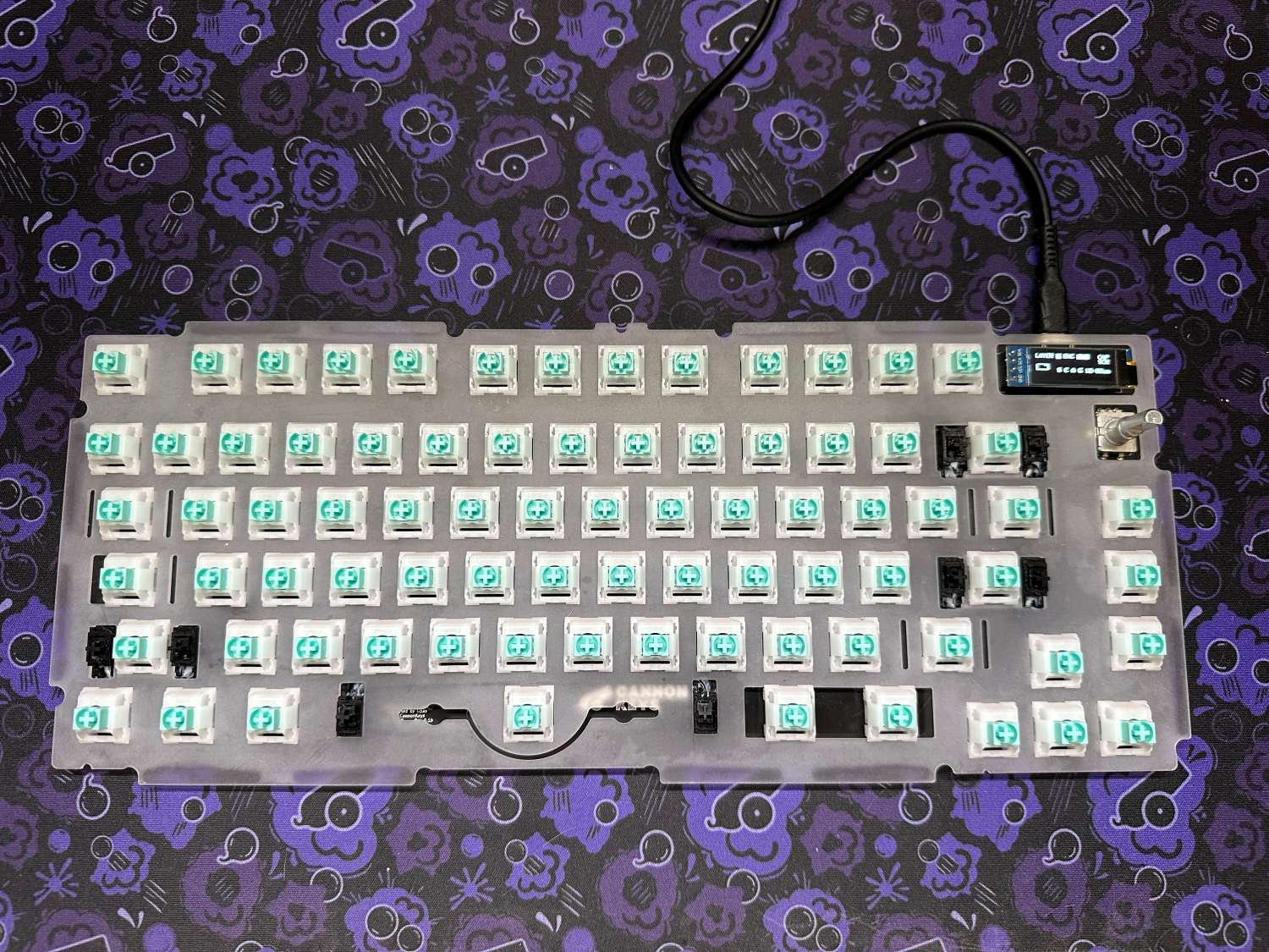
-
With all the switches now properly installed, put the knob on the encoder, and move onto the next section of the guide! If you're someone who enjoys tinkering with your builds and plans on rebuilding often, we recommend putting a little lube on the inside of the knob as the fit is quite snug. The lube makes removing the knob safer and easier.
Case assembly
With the PCB and plate assembled, you are now ready for the final steps for your build. Grab your case, feet, and gaskets and continue on with the guide!
-
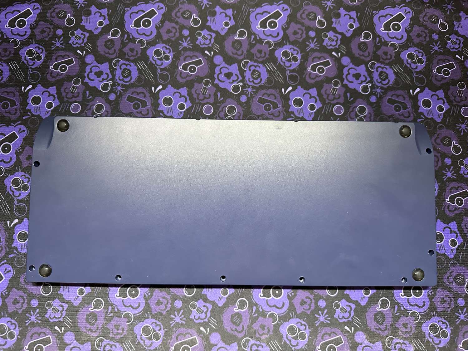
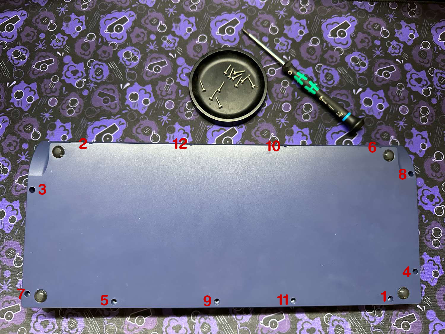
Install the included feet onto the bottom case.
-
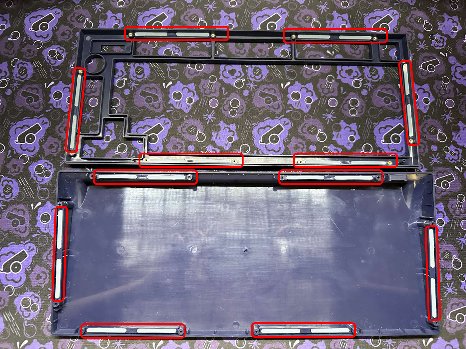
If your case is screwed together, unscrew the 12 hex screws, and separate the top and bottom. Into each of the 24 little pockets, install the gaskets. If you look closely, you will notice that each of the little case pieces where you're installing the bottom gaskets is actually removeable. While this does allow for further customization, for your first build we recommend leaving all of them installed.
-
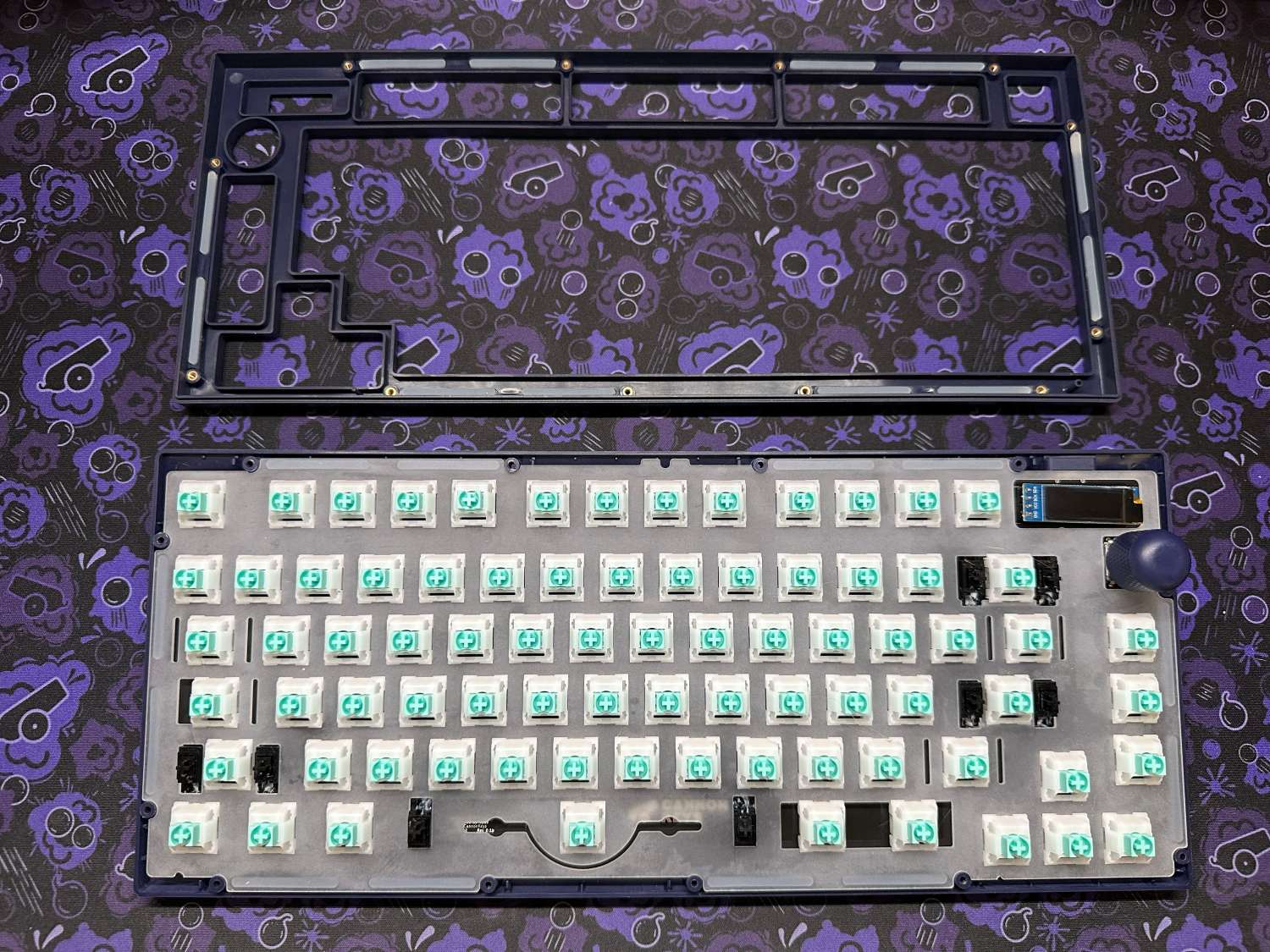
Next, drop the PCB & plate assembly into the bottom case, and then carefully put the top case on.
-
With everything installed, flip over the case and install the 12 hex screws. To help avoid case warping and achieve a more even gasket compression, install screws opposite eachother in a criss-cross pattern as seen below. You don't need to tighten these too much - we recommend stopping once you start to feel resistance.
-
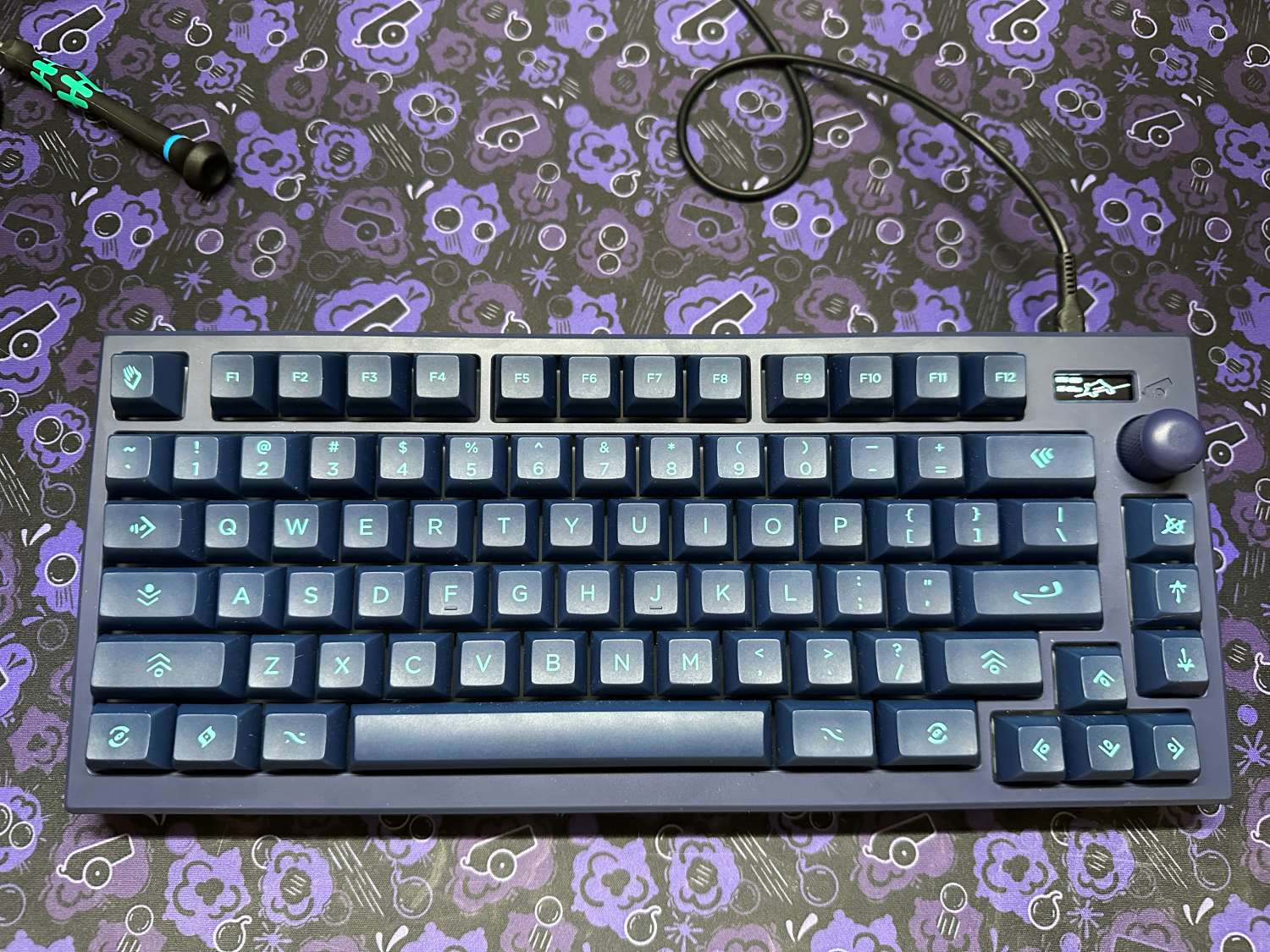
With the screws installed, flip over your keyboard, add keycaps, plug it in, and your build is complete!
Additional information
Your build is done - now what? Below we'll compile some useful information as well as some other things you can do to further customize your build.
Keymap customization and rebinding
Sat75 X is compatible out of the box with VIA. We recommend using the online configurator in a chromium browser like chrome.
The knob and OLED screen also have some customizations that can be applied. Check out the Satisfaction75 user guide for more information on those. The customizations include setting the clock time, and custom rebinds for encoder actions.
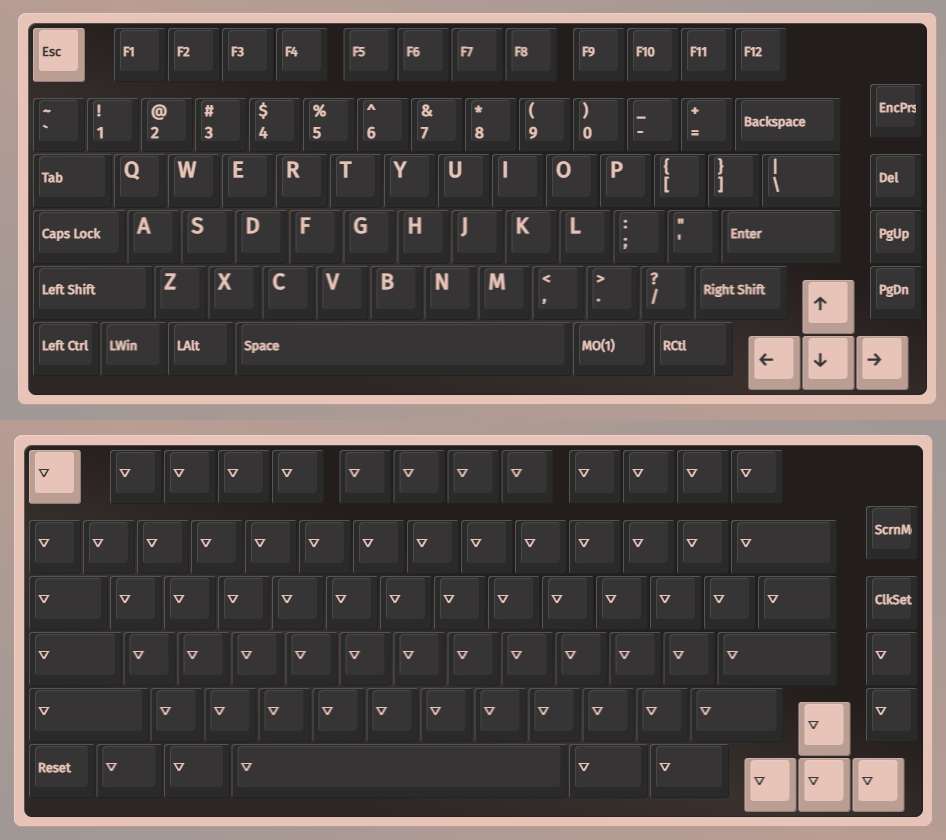
The default keymap for the Sat75 X hotswap PCB
Battery
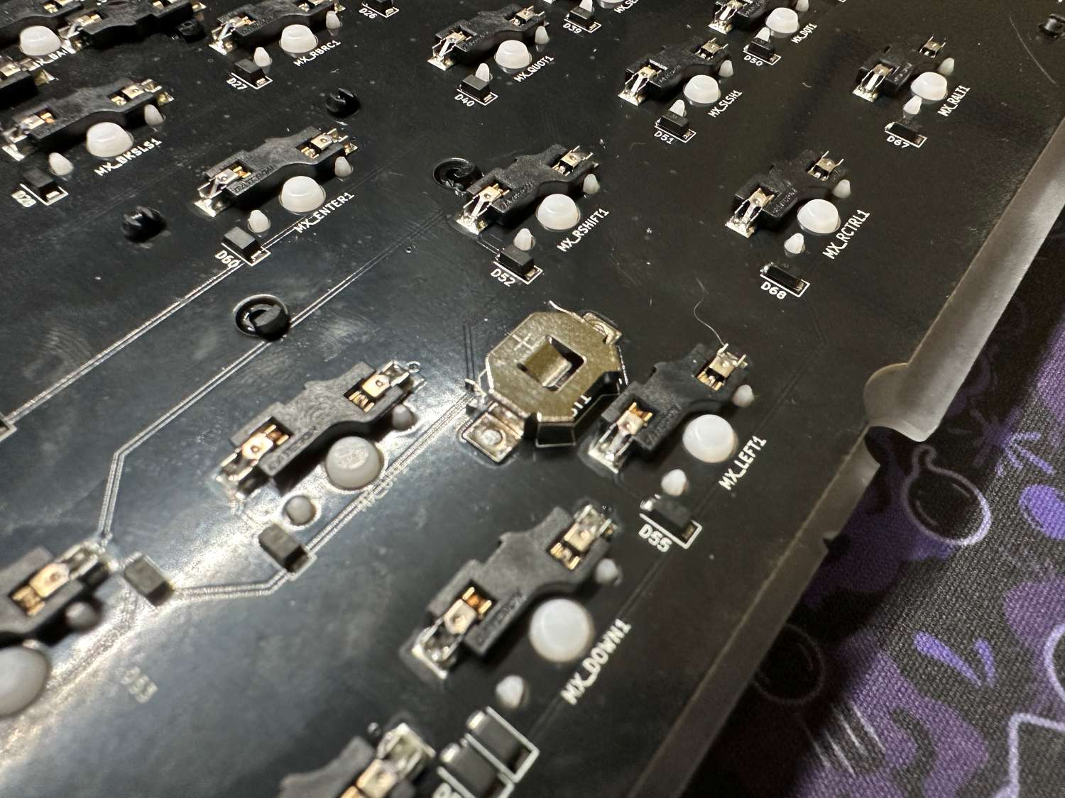
The Sat75 X firmware includes a RTC that is displayed on the screen. To keep the time accurate even while unplugged, you will need to install a CR1025 battery into the PCB. The battery gets slid into the small holder positive side up.
Black Screen Issue
If you're experiencing a screen that will not turn on after your computer sleeps without unplugging the keyboard and plugging back in, we have a fix for you! There are two options:
- Option 1 is to add the custom keycode "0x7C01" to your keymap using the GIF below as a guide. This keycode is QK_Reset, which resets the PCB quickly, effectively acting as an unplug replug action in software. When you wake up your PC, simply input the shortcut you mapped it to. If you're using a solder PCB, use this option.
- Option 2 is to flash updated hotswap firmware (the same one linked below), and which puts the QK_Reset code in the Esc key location on layer one. Simply flash, and hold the MO(1)/FN key and tap the esc key to get your screen back on.
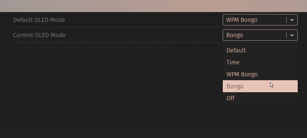
Incorrect OLED modes displayed in VIA
If you're using the default hotswap PCB, you can sideload this .json file into via. We have a guide on sideloading a .json here.
Flashing
While you should not need to flash the Sat75 X, we have a standard PCB flashing guide here.
On the bottom of the PCB you will see a switch with 0 and 1 labeled, as well as a little button.
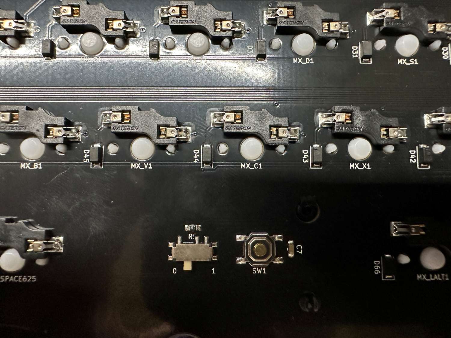
- Switch in 0 position allows the keyboard to function normally
- Switch in 1 position puts the keyboard into a mode that allows firmware flashing
- The button resets the PCB, putting it into whichever mode you've selected. You can also unplug the keyboard and plug back in.
Firmware downloads
Not seeing what you're looking for?
Not to worry! While we do have a community on Discord, if you are running into issues with your build we recommend contacting our official support team through the widget on the contact us page of our website.